 Honda Accord: Electrical Compass Unit Input
Test
Honda Accord: Electrical Compass Unit Input
Test
1. Remove the rear shelf (see page 20-128).
2. Loosen the bolts (A), then pull out the electrical compass unit bracket (B).
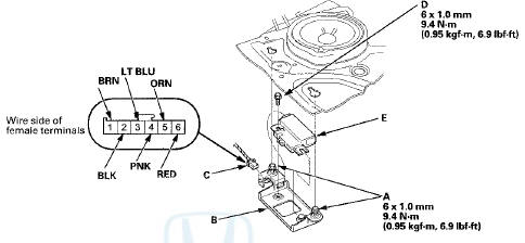
3. Disconnect the 6P connector (C) and remove the mounting bolt ( D ) , then pull out the electrical compass unit (E).
4. Inspect the connector and socket terminals to make sure they are all making good contact.
• If the terminals are bent, loose, or corroded, repair them as necessary, and recheck the system.
• If the terminals look OK, go to step 5.
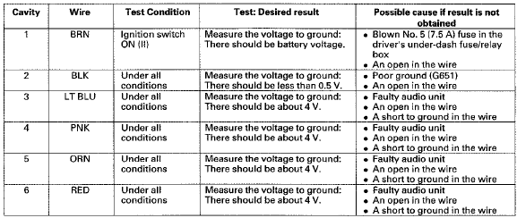
5. Reconnect the electrical compass unit BP connector. Turn the ignition switch to ON (ll), and do the following input tests at the connectors.
• If any test indicates a problem, find and correct the cause, then recheck t h e system.
• If all input t e s t s p r o v e OK, t h e electrical compass unit is faulty; replace it, and do the compass calibration (see page 23-247).
 Electrical Compass Zone Selection
and Calibration
Electrical Compass Zone Selection
and Calibration
NOTE:
• You should do this procedure any time the electrical
compass unit is replaced.
• You should do this procedure in an open area away
from buildings, power lines, and other vehicl ...

See also:
Daytime Running Lights
The high beam headlights come on slightly dimmer than normal when the
following
conditions have been met:
The parking/daytime running lights come on when the following conditions have
been ...
Wheel Bolt Replacement
Special Tools Required
B a i l Joint Remover, 28 mm 07MAC-SL0A202
- Do not use a hammer or impact tools (pneumatic or
electric) to remove and install the wheel bolts.
- Be careful not to damag ...