 Honda Accord: DTC Troubleshooting
DTC P062F:
Powertrain Control Module (PCM) Internal Control Module Keep Alive Memory (KAM) Error
NOTE: Before you troubleshoot record all freeze data and any on-board snapshot with the HDS, and review General Troubleshooting Information (see page 14-4).
1. Turn the ignition switch to ON (II).
2. Clear the DTC with the HDS.
3. Check for Pending or Confirmed DTCs in the PGM-FI SYSTEM with the HDS.
Is DTC P062F indicated in the PGM-FI SYSTEM? YES
-Go to the DTC P062F troubleshooting in the PGM-FI System (see page 11 -136).
NO
-Go to step 4.
4. Check for Pending or Confirmed DTCs in the A/T SYSTEM with the HDS.
Is DTC P062F indicated in the AIT SYSTEM? YES
-Go to step 5.
NO
-lntermittent failure, the system is OK at this time.
If any other Pending or Confirmed DTCs were indicated, go to the indicated DTCs troubleshooting.
5. Update the PCM if it does not have the latest software (see page 11-203), or substitute a known-good PCM (see page 11-7).
6. Start the engine, and wait for at least 2 minutes.
7. Check for Pending or Confirmed DTCs in the A/T SYSTEM with the HDS.
Is DTC P062F indicated in the A/T SYSTEM? YES
-Check for poor connections or loose terminals at the PCM. If the PCM was updated, substitute a known-good PCM (see page 11 -7), then go to step 6. If the PCM was substituted, go to step 1.
NO
-Go to step 8.
8. Monitor the OBD STATUS for P062F in the DTCs MENU with the HDS.
Does the HDS indicate PASSED? YES
-lf the PCM was updated, troubleshooting is complete. If the PCM was substituted, replace the original PCM (see page 11-204). If any other Pending or Confirmed DTCs were indicated in step 7, go to the indicated DTCs troubleshooting.
NO
-lf the HDS indicates FAILED, check for poor connections or loose terminals at the PCM. If the PCM was updated, substitute a known-good PCM (see page 11-7), then go to step 6. If the PCM was substituted, go to step 1. If the HDS indicates NOT COMPLETED, go to step 6.
DTC P0705:
Short in Transmission Range Switch Circuit (Multiple Shift-position Input)
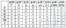
O:0N X-.OFF Do the transmission range switch signals match? YES-
lntermittent failure, the system is OK at this time.
NO
-Go to step 3.
3. Compare the ATPP, ATPR, ATPN, ATPD, ATPD3, ATP2-1, ATPFWD, and ATPRVS inputs with the HDS to the table in step 2, in each shift lever position.
Are any transmission range switch signals ON in all shift lever position? YES
-Go to step 9.
NO
-Go to step 4.
4. Turn the ignition switch to LOCK (0).
5. Disconnect the transmission range switch connector.
6. Connect the transmission range switch connector terminal that incorrectly indicates ON in step 3 to body ground with a jumper wire.
7. Turn the ignition switch to ON (II).
8. Compare the ATPP, ATPR, ATPN, ATPD, ATPD3, ATP2-1, ATPFWD, and ATPRVS inputs with the HDS to the table in step 2.
Do multiple transmission range switch signals indicate ON? .
YES
-Repair short in the wires between the transmission range switch and the PCM, refer to the
following table.

9. Turn the ignition switch to LOCK (0).
10. Disconnect the transmission range switch connector.
11. Turn the ignition switch to ON (II).
12. Check the abnormal transmission range switch signal that remained on with the HDS.
Do any transmission range switch signals remain ON? YES
-Go to step 13.
* NO
-Replace the transmission range switch (see page 14-240).
13. Check for continuity to body ground in the circuit which remained ON, see table in step 2.
Does the circuit that indicated ON have continuity to ground? YES
-Repair short to body ground in the wire between the transmission range switch and the PCM.
NO
-Replace the PCM (see page 11-204)
DTC P0706:
Open in Transmission Range Switch Circuit
NOTE: -Before you troubleshoot record all freeze data and any on-board snapshot with the HDS, and review General Troubleshooting Information (see page 14-4).
-This code is caused by an electrical circuit problem and cannot be caused by a mechanical problem in the transmission.
1. Make sure the shift cable is adjusted properly (see page 14-232).
2. Turn the ignition switch to ON (II).
3. Compare the ATPP, ATPR, ATPN, ATPD, ATPD3, ATP2-1, ATPFWD, and ATPRVS inputs with the HDS to the following table.
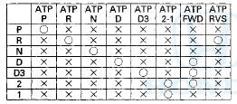
O: ON X-.OFF
Do the transmission range switch signals match? YES
-lntermittent failure, the system is OK at this time.
NO
-Go to step 4.
4. Compare the ATPP, ATPR, ATPN, ATPD, ATPD3, ATP2-1, ATPFWD, and ATPRVS inputs with the HDS to the table in step 3, in each shift lever position
Do all shift positions remain OFF? YES
-Go to step 12.
NO
-Go to step 5.
5. Turn the ignition switch to LOCK (0).
6. Disconnect the transmission range switch connector.
7. Connect the transmission range switch connector terminal which did not indicate ON in step 4 to body ground with a jumper wire.
8. Turn the ignition switch to ON (II).
9. Check the transmission range switch signals that did not indicate ON with the HDS.
Does the transmission range switch indicate ON? YES
-Replace the transmission range switch (see page 14-240).
NO
-Go to step 10.
10. Turn the ignition switch to LOCK (0).
11. Check for continuity between the transmission range switch circuit terminal and the PCM terminal of the input which indicated OFF, refer to the following table.
Is there continuity? YES
-Replace the PCM (see page 11-204).
NO
-Repair open in the wire between the transmission range switch and the PCM.
12. Turn the ignition switch to LOCK (0).
13. Disconnect the transmission range switch connector.
14. Check for continuity between transmission range switch connector terminal No. 10 and body ground.
TRANSMISSION RANGE SWITCH CONNECTOR
Wire side of female terminals
Is there continuity? YES
-Replace the transmission range switch (see page 14-240).
NO
-Repair open in the wire between the transmission range switch and body ground (G101) (see page 22-18), or repair poor body ground (G101).
DTC P0711:
Problem in ATF Temperature Sensor Circuit
NOTE: -Before you troubleshoot, record all freeze data and any on-board snapshot with the HDS, arid review General Troubleshooting Information (see page 14-4).
-This code is caused by an electrical circuit problem and cannot be caused by a mechanical problem in the transmission.
1. Turn the ignition switch to ON (II), and wait for 20 secounds.
2. Check the ATF temperature with the HDS in the A/T Data List.
Does the ATF Temperature with indicate —4 °F (-20 °C)
YES
-Go to step 3.
NO
-Go to step 5.
3. Start the engine, and warm it up to normal operating temperature (the radiator fan comes on).
4. Check the ATF Temperature with the HDS in the A/T Date List.
Does the ATF Temperature remain —4 °F (—20 °C) or below? YES
-Replace the ATF temperature sensor (see page 14-189), then go to step 8.
NO
-lntermittent failure, the system is OK at this time.
If there is an abnormal temperature rise in the ATF temperature sensor, go to step 16.
5. Check the ATF Temperature with the HDS in the A/T Data List.
Does the ATF temperature exceed 230 В°F (110 В°C)? YES
-Go to step 6.
NO
-lntermittent failure, the system is OK at this time.
6. Leave the engine off until the Engine Coolant Temperature reads 122 В°F (50 В°C) with the HDS in the A/T Date List.
7. Check the ATF Temperature with the HDS in the A/T Data List.
Does the ATF temperature remain 230 В°F(110 В°C) or higher? YES
-Replace the ATF temperature sensor (see page 14-189), then go to step 8.
NO
-lntermittent failure, the system is OK at this time.
If there is an abnormal temperature rise in the ATF temperature sensor, go to step 16.
8. Turn the ignition switch to ON (II).
9. Clear the DTC with the HDS.
10. Start the engine, and warm it up to normal operating temperature (the radiator fan comes on).
11. I urn the ignition switch to LOCK (0), and allow the engine to coolant cool to the outside air temperature (the Engine Coolant Temperature reads the same as the outside air temperature).
12. Block the rear wheels and raise the front of the vehicle, make sure it is securely supported, and allow the front wheels to rotate freely, or raise the vehicle on a lift.
13. Turn the ignition switch to ON (II), and wait for 20 seconds, then start the engine. Warm the engine up to normal operating temperature (the radiator fan comes on). Start off in D, accelerate with the throttle opened at least 4 degrees, and run the vehicle at speeds over 19 mph (30 km/h) for at least 5 minutes.
Or test-drive the vehicle for at least 20 seconds while the ATF temperature reads - 4 В°F to 230 В°F ( - 2 0 В°C to 110 В°C) by monitoring with the HDS. Slow down, and stop the wheels.
14. Check for Pending or Confirmed DTCs with the HDS.
Is DTC P0711 indicated? YES
-Check for poor connections or loose terminals between the ATF temperature sensor and the PCM, then go to step 1.
NO
-Go to step 15.
15. Monitor the OBD status for P0711 in the DTCs MENU with the HDS.
Does the HDS indicate PASSED? YES
-Troubleshooting is complete. If any other Pending or Confirmed DTCs were indicated in step 14, go to the indicated DTCs troubleshooting.
NO
-lf the HDS indicates FAILED, check for poor connections and loose terminals at the ATF temperature sensor and the PCM, then go to step 1. If the HDS indicates NOT COMPLETED, go to step 10.
16. Update the PCM if it does not have the latest software (see page 11-203), or substitute a known-good PCM (see page 11-7).
17. Turn the ignition switch to ON (II). Start the engine, and warm the engine up to normal operating temperature (the radiator fan comes on).
18. Turn the ignition switch to LOCK (0), and allow the engine to coolant cool to the ambient air temperature (the ECT SENSOR reads the same as the ambient air temperature).
19. Block the rear wheels and raise the front of the vehicle, make sure it is securely supported, and allow the front wheels to rotate freely, or raise the vehicle on a lift.
20. Turn the ignition switch to ON (II), and wait for 20 seconds, then start the engine. Warm the engine up to normal operating temperature (the radiator fan comes on). Start off in D, accelerate with the throttle opened at least 4 degrees, and run the vehicle at speeds over 19 mph (30 km/h) for at least 5 minutes.
Or test-drive the vehicle for at least 20 seconds while the ATF temperature reads - 4 В°F to 230 В°F ( - 2 0 В°C to 110 В°C) by monitoring with the HDS. Slow down, and stop the wheels.
21. Check for Pending or Confirmed DTCs with the HDS.
Is DTC P0711 indicated? YES
-Check for poor connections or loose terminals between the ATF temperature sensor and the PCM. If the PCM was updated, substitute a known-good PCM (see page 11-7), then go to step 20. If the PCM was substituted, go to step 1.
NO
-Go to step 22.
22. Monitor the OBD status for P0711 in the DTCs MENU with the HDS.
Does the HDS indicate PASSED? YES
-lf the PCM was updated, troubleshooting is complete. If the PCM was substituted, replace the original PCM (see page 11-204). If any other Pending or Confirmed DTCs were indicated in step 21, go to the indicated DTCs troubleshooting.
NO
-lf the HDS indicates FAILED, check for poor connections or loose terminals between the ATF temperature sensor and the PCM. If the PCM was updated, substitute a known-good PCM (see page 11-7), then go to step 17. If the PCM was substituted, go to step 1. If the HDS indicates NOT COMPLETED, go to step 17.
DTC P0712:
Short in ATF Temperature Sensor Circuit
NOTE: -Before you troubleshoot, record all freeze data and any on-board snapshot with the HDS, and review General Troubleshooting Information (see page 14-4).
-This code is caused by an electrical circuit problem and cannot be caused by a mechanical problem in the transmission.
1. Turn the ignition switch to ON (II).
2. Check the ATF Temp Sensor (V) in the Data List with the HDS.
Is the ATF Temp Sensor (V) 0.07 V or less? YES
-Go to step 3. NO
-lntermittent failure, the system is OK at this time.
Check for an intermittent short to body ground in the wire between the ATF temperature sensor and the PCM.B 3. Turn the ignition switch to LOCK (0).
4. Disconnect the shift solenoid wire harness connector.
5. Turn the ignition switch to ON (II).
6. Check the ATF Temp Sensor (V) in the Data List with the HDS.
Is the ATF Temp Sensor (V) 0.07 V or less? YES
-Go to step 7.
NO
-Replace the ATF temperature sensor (see page 14-189), then go to step 11.
7. Turn the ignition switch to LOCK (0).
8. Jump the SCS line with the HDS.
9. Disconnect PCM connector B (49P).
10. Check for continuity between shift solenoid wire harness connector terminal No. 6 and body ground.
SHIFT SOLENOID WIRE HARNESS CONNECTOR
Wire side of female terminals
Is there continuity? YES
-Repair short to body ground in the wire between PCM connector terminal B28 and shift solenoid wire harness connector terminal No. 6, then go to step 11.
NO
-Go to step 17.
11. Reconnect all connectors.
12. Turn the ignition switch to ON (II).
13. Clear the DTC with the HDS.
14. Start the engine with the shift lever in P, and wait for at least 20 seconds.
15. Check for Pending or Confirmed DTCs with the HDS.
Is DTC P0712 indicated? YES
-Check for intermittent short to body ground in the wire between the ATF temperature sensor and the PCM, then go to step 1.
NO
-Go to step 16.
16. Monitor the OBD STATUS for P0712 in the DTCs MENU with the HDS.
Does the HDS indicate PASSED? YES
-Troubleshooting is complete. If any other Pending or Confirmed DTCs were indicated in step 15, go to the indicated DTCs troubleshooting.
NO
-lf the HDS indicates FAILED, check for intermittent short to body ground in the wire between the ATF temperature sensor and the PCM, then go to step 1. If the HDS indicates NOT COMPLETED, go to step 14.
17. Reconnect all connectors.
18. Update the PCM if it does not have the latest software (see page 11-203), or substitute a known-good PCM (see page 11-7).
19. Start the engine with the shift lever in P, and wait for at least 20 seconds.
20. Check for Pending or Confirmed DTCs with the HDS.
Is DTC P0712 indicated? YES
-Check for intermittent short to body ground in the wire between the ATF temperature sensor and the PCM. If the PCM was updated, substitute a known-good PCM (see page 11-7), then go to step 19.
If the PCM was substituted, go to step 1.
NO
-Go to step 21.
21. Monitor the OBD STATUS for P0712 in the DTCs MENU with the HDS.
Does the HDS indicate PASSED? YES
-lf the PCM was updated, troubleshooting is complete. If the PCM was substituted, replace the original PCM (see page 11-204). If any other Pending or Confirmed DTCs were indicated in step 20, go to the indicated DTCs troubleshooting.
NO
-lf the HDS indicates FAILED, check for intermittent short to body ground in the wire between the ATF temperature sensor and the PCM. If the PCM was updated, substitute a known-good PCM (see page 11-7), then go to step 19. If the PCM was substituted, go to step 1. If the HDS indicates NOT COMPLETED, go to step 19.
DTC P0713:
Open in ATF Temperature Sensor Circuit
NOTE: -Before you troubleshoot, record all freeze data and any on-board snapshot with the HDS, and review General Troubleshooting Information (see page 14-4).
-This code is caused by an electrical circuit problem and cannot be caused by a mechanical problem in the transmission.
1. Turn the ignition switch to ON (II).
2. Check the ATF Temp Sensor (V) in the Data List with the HDS.
Does the ATF Temp Sensor (V) exceed 4.93 V? YES
-Go to step 3.
NO
-lntermittent failure, the system is OK at this time.
Check for poor connections or loose terminals between the ATF temperature sensor and the PCM.Si 3. Turn the ignition switch to LOCK (0).
4. Disconnect the shift solenoid wire harness connector.
5. Connect shift solenoid wire harness connector terminal No. 6 to body ground with a jumper wire.
SHIFT SOLENOID WIRE HARNESS CONNECTOR
Wire side of female terminals
6. Turn the ignition switch to ON (II).
7. Check the ATF Temp Sensor (V) in the Data List with the HDS.
Does the ATF Temp Sensor (V) read 0.07 V or below? YES
-Go to step 8.
NO
-Go to step 13.
8. Turn the Ignition switch to LOCK (0).
9. Remove the jumper wire from the shift solenoid wire harness connector.
10. Connect shift solenoid wire harness connector terminals No. 6 and No. 7 with a jumper wire
SHIFT SOLENOID WIRE HARNESS CONNECTOR
Wire side of female terminals
11. Turn the ignition switch to ON (II).
12. Check the ATF Temp Sensor (V) in the Data List with the HDS.
Does the ATF Temp Sensor (V) read 0.07 V or below? YES
-Replace the ATF temperature sensor (see page 14-189), then go to step 17.
NO
-Repair open in the wire between PCM connector terminal B34 and the shift solenoid wire harness connector terminal No.7, then go to step 17.
13. Turn the ignition switch to LOCK (0).
14. Jump the SCS line with the HDS.
15. Disconnect PCM connector B (49P).
16. Check for continuity between PCM connector terminal B28 and shift solenoid wire harness connector terminal No. 6.
Is there continuity? YES
-Check for poor connections or loose terminals between the ATF temperature sensor and the PCM. If the connections are OK, go to step 23.
NO
-Repair open in the wire between PCM connector terminal B28 and the shift solenoid wire harness connector terminal No.6, then go to step 17.
17. Reconnect all connectors.
18. Turn the ignition switch to ON (II).
19. Clear the DTC with the HDS.
20. Start the engine with the shift lever in P, and wait for at least 20 seconds.
21. Check for Pending or Confirmed DTCs with the HDS.
Is DTC P0713 indicated? YES
-Check for poor connections or loose terminals between the ATF temperature sensor and the PCM, then go to step 1.
NO
-Go to step 22.
22. Monitor the OBD STATUS for P0713 in the DTCs MENU with the HDS.
Does the HDS indicate PASSED? YES
-Troubleshooting is complete. If any other Pending or Confirmed DTCs were indicated in step 21, go to the indicated DTCs troubleshooting.
NO
-lf the HDS indicates FAILED, check for poor connections or loose terminals between the ATF temperature sensor and the PCM, then go to step 1. If the HDS indicates NOT COMPLETED, go to step 20.
23. Reconnect all connectors.
24. Update the PCM if it does not have the latest software (see page 11-203), or substitute a known-good PCM (see page 11-7).
25. Start the engine with the shift lever in P, and wait for at least 20 seconds.
26. Check for Pending or Confirmed DTCs with the HDS.
Is DTC P0713 indicated? YES
-Check for poor connections or loose terminals between the ATF temperature sensor and the PCM. If the PCM was updated, substitute a known-good PCM (see page 11-7), then go to step 25. If the PCM was substituted, go to step 1.
NO
-Go to step 27.
27. Monitor the OBD STATUS for P0713 in the DTCs MENU with the HDS.
Does the HDS indicate PASSED? YES
-lf the PCM was updated, troubleshooting is complete. If the PCM was substituted, replace the original PCM (see page 11-204). If any other Pending or Confirmed DTCs were indicated in step 26, go to the indicated DTCs troubleshooting.
NO
-lf the HDS indicates FAILED, check for poor connections or loose terminals between the ATF temperature sensor and the PCM. If the PCM was updated, substitute a known-good PCM (see page 11-7), then go to step 25. If the PCM was substituted, go to step 1. If the HDS indicates NOT COMPLETED, go to step 25.
DTC P0716
: Problem In Input Shaft (Mainshaft) Speed Sensor Circuit
DTC P0721:
Problem in Output Shaft .
(Countershaft) Speed Sensor Circuit
NOTE: -Before you troubleshoot, record all freeze data and.
any on-board snapshot with the HDS, and review General Troubleshooting Information (see page 14-4).
-This code is caused by an electrical circuit problem and cannot be caused by a mechanical problem in the transmission.
1. Turn the ignition switch to ON (II).
2. Clear the DTC with the HDS.
3. Rioou the rear Vwli^cis and raise the front of the vehicle, make sure it is securely supported, and allow the front wheels to rotate freely, or raise the vehicle on a lift.
4. Start the engine, disable the VSA by pressing the VSA OFF button, run the vehicle with the shift lever in D, and at speeds over 12 mph (20 km/h) for at least 10 seconds. Slow down, and stop the wheels.
5. Check for Pending or Confirmed DTCs with the HDS.
Is DTC P0718 or P0723 indicated?
YES
-Go to the DTC P0718 trobleshooting (see page 14-87) or the DTC P0723 trobleshooting (see page 14-89).
NO
-Go to step 6.
6. Check for Pending or Confirmed DTCs with the HDS.
Is DTC P0716 or P0721 indicated? YES
-Go to step 7.
NO
-lntermittent failure, the system is OK at this time.
7. Check the input shaft (mainshaft) speed sensor or the output shaft (countershaft) speed sensor for poor connection and proper installation.
Is the connection and installation OK? YES
-Replace the input shaft (mainshaft) speed sensor (see page 14-187) or the output shaft (countershaft) speed sensor (see page 14-188), then go to step 8.
N0
-Connect the speed sensor connector and reinstall the speed sensor, then go to step 8.
8. Turn the ignition switch to ON (II), 9. Clear the DTC with the HDS.
10. Start the engine, disable the VSA by pressing the VSA OFF button, run the vehicle with the shift lever in D, and at speeds over 12 mph (20 km/h) for at least 10 seconds. Slow down, and stop the wheels.
11. Check for Pending or Confirmed DTCs with the HDS.
Is DTC P0716 or P0721 indicated? YES
-Go to step 1.
NO
-Trobleshooting is complete.
DTC P0717:
Problem In Input Shaft (Mainshaft) Speed Sensor Circuit (No Signal Input)
DTC P0718:
Input Shaft (Mainshaft) Speed Sensor Intermittent Failure
NOTE: -Before you troubleshoot, record all freeze data and any on-board snapshot with the HDS, and review General Troubleshooting Information (see page 14-4).
-This code is caused by an electrical circuit problem and cannot be caused by a mechanical problem in the transmission.
1. Turn the ignition switch to ON (II).
2. Clear the DTC with the HDS.
3. Block the rear wheels and raise the front of the vehicle, make sure it is securely supported, and allow the front wheels to rotate freely, or raise the vehicle on a lift.
4. Start the engine, disable the VSA by pressing the VSA OFF button, run the vehicle with the shift lever in D, and at speeds over 12 mph (20 km/h) for at least 10 seconds. Compare the Input Shaft (Mainshaft) Speed and the Output Shaft (Countershaft) Speed in the Data List with the HDS. Slow down, and stop the wheels.
Arethe speeds about the same? YES
-lntermittent failure, the system is OK at this time.
NO
-Go to step 5.
5. Turn the ignition switch to LOCK (0).
6. Disconnect the input shaft (mainshaft) speed sensor connector.
7 Turn the ignition switch to ON (II).
8. Measure the voltage between input shaft (mainshaft) speed sensor connector terminal No. 1 and body ground.
INPUT SHAFT (MAINSHAFT) SPEED SENSOR CONNECTOR
Wire side of female terminals
Is there about 5 V? YES
-Go to step 9.
NO
-Repair open in the wire between PCM connector terminal B19 and the input shaft (mainshaft) speed sensor, then go to step 16.
9. Measure the voltage between input shaft (mainshaft) speed sensor connector terminal No. 2 and body ground.
INPUT SHAFT (MAINSHAFT) SPEED SENSOR CONNECTOR
Wire side of female terminals
Is there about 5 V? YES
-Go to step 10.
NO
-Go to step 12.
10. Turn the ignition switch to LOCK (0).
11. Check for continuity between input shaft (mainshaft) speed sensor connector terminal No. 3 and body ground.
INPUT SHAFT (MAINSHAFT) SPEED SENSOR CONNECTOR
Wire side of female terminals
Is there continuity? YES
-Replace the input shaft (mainshaft) speed sensor (see page 14-187), then go to step 19.
NO
-Repair open in the wire between the input shaft (mainshaft) speed sensor connector and the PCM connector terminal B34, then go to step 16.
12. Turn the ignition switch to LOCK (0).
13. Jump the SCS line with the HDS.
14. Disconnect PCM connector B (49P).
15. Check for continuity between input shaft (mainshaft) speed sensor connector terminal No. 2 and body ground.
INPUT SHAFT (MAINSHAFT) SPEED SENSOR CONNECTOR
Wire side of female terminals
Is there continuity? YES
-Repair short to body ground in the wire between PCM connector terminal B18 and the input shaft (mainshaft) speed sensor connector, then go to step 16.
NO
-Repair open in the wire between PCM connector terminal B37 and the input shaft (mainshaft) speed sensor, then go to step 16.
16. Reconnect all connectors.
17. Turn the ignition switch to ON (II).
18. Clear the DTC with the HDS.
19. Start the engine, disable the VSA by pressing the VSA OFF button, run the vehicle with the shift lever in D, and at speeds over 12 mph (20 km/h) for at least 10 seconds. Compare the Input Shaft (Mainshaft) Speed and the Output Shaft (Countershaft) Speed in the Data List with the HDS. Slow down, and stop the wheels.
Arethe speeds about the same? YES
-Trobleshooting is complete.
NO
-Go to step 1.
DTC P0722:
Problem in Output Shaft (Countershaft) Speed Sensor (No Signal Input)
DTC P0723:
Output Shaft (Countershaft) Speed Sensor Intermittent Failure
NOTE: -Before you troubleshoot, record all freeze data arid any on-board snapshot with the HDS, and review General Troubleshooting Information (see page 14-4).
-This code is caused by an electrical circuit problem and cannot be caused by a mechanical problem in the transmission.
1. Turn the ignition switch to ON (II).
2. Clear the DTC with the HDS.
3. Block the rear wheels and raise the front of the vehicle, make sure it is securely supported, and allow the front wheels to rotate freely, or raise the vehicle on a lift.
4. Start the engine, disable the VSA by pressing the VSA OFF button, run the vehicle with the shift lever in D, with the engine speed above 2,000 rpm for at least 10 seconds. Compare the Output Shaft (Countershaft) Speed and the Input Shaft (Mainshaft) Speed in the Data List with the HDS. Slow down, and stop the wheels.
Arethe speeds about the same? YES
-lntermittent failure, the system is OK at this time.
NO
-Go to step 5.
5. Turn the ignition switch to LOCK (0).
6. Disconnect the output shaft (countershaft) speed sensor connector.
7. Turn the ignition switch to ON (II).
8. Measure the voltage between output shaft (countershaft) speed sensor connector terminal No. 1 and body ground.
OUTPUT SHAFT (MAINSHAFT) SPEED SENSOR CONNECTOR
Wire side of female terminals
Is there about 5 V? YES
-Go to step 9.
NO
-Repair open in the wire between PCM connector terminal C13 and the output shaft (countershaft) speed sensor, then go to step 16.
9. Measure the voltage between output shaft (countershaft) speed sensor connector terminal No. 2 and body ground.
OUTPUT SHAFT (MAINSHAFT) SPEED SENSOR CONNECTOR
Wire side of female terminals
Is there about 5 V? YES
-Go to step 10.
NO
-Go to step 12.
10. Turn the ignition switch to LOCK (0).
11. Check for continuity between output shaft (countershaft) speed sensor connector terminal No. 3 and body ground.
OUTPUT SHAFT (MAINSHAFT) SPEED SENSOR CONNECTOR
Wire side of female terminals
Is there continuity? YES
-Replace the output shaft (countershaft) speed sensor (see page 14-188), then go to step 19.
NO
-Repair open in the wire between the PCM connector terminal C14 and the output shaft (countershaft) speed sensor, then go to step 16.
12. Turn the ignition switch to LOCK (0).
13. Jump the SCS line with the HDS.
14. Disconnect PCM connector B (49P).
15. Check for continuity between output shaft (countershaft) speed sensor connector terminal No. 2 and body ground.
OUTPUT SHAFT (MAINSHAFT) SPEED SENSOR CONNECTOR
Wire side of female terminals
Is there continuity? YES-
Repair short to body ground in the wire between PCM connector terminal B38 and the output shaft (countershaft) speed sensor connector, then go to step 16.
NO
-Repair open in the wire between PCM connector terminal B38 and output shaft (countershaft) speed sensor, then go to step 16.
16. Reconnect ail connectors.
17. Turn the ignition switch to ON (II).
18. Clear the DTC with the HDS.
19. Start the engine, disable the VSA by pressing the VSA OFF button, run the vehicle with the shift lever in D, with the engine speed above 2,000 rpm for at least 10 seconds. Compare the Output Shaft (Countershaft) Speed and the Input Shaft (Mainshaft) Speed in the Data List with the HDS. Slow down, and stop the wheels.
Arethe speeds about the same? YES
-Trobleshooting is complete.H NO
-Go to step 1.
DTC P0731:
Problem in 1st Clutch and 1st Clutch Hydraulic Circuit (1st Gear Incorrect Ratio)
NOTE: Before you troubleshoot, record all freeze data and any on-board snapshot with the HDS, and review General Troubleshooting Information (see page 14-4).
1. Warm up the engine to normal operating temperature (the radiator fan comes on).
2. Make sure that the transmission is filled to the proper level, and check for fluid leaks.
3. Drain the ATF (see step 3 on page 14-192) through a strainer. Inspect the strainer for metal debris or excessive clutch material.
Does the strainer have metal debris or excessive clutch material? YES-
Replace the transmission, then go to step 12.
NO
-Replace the ATF (see page 14-192), then go to step 4.
4. Test stall speed in D (see page 14-174).
Is the stall speed within the service limits? YES
-Go to step 5.
NO
-Shift valves A and D are stuck. Repair these valves and the related hydraulic circuit, or replace the transmission, then go to step 12.
5. Measure the line pressure (see page 14-175).
Is the line pressure within the service limit? YES
-Go to step 6.
NO
-Repair the ATF pump and the regulator valve, or replace the transmission, then go to step 12.
6. Measure the 1st clutch pressure (see page 14-175).
Is the 1st clutch pressure within the service limits? YES
-Go to step 7.
NO
-Shift valves B and C are stuck. Repair these valves and the related hydraulic circuit, or replace the transmission, then go to step 12.
7. Turn the ignition switch to ON (II).
8. Clear the DTC with the HDS.
9. Test-drive the vehicle in 1st gear, with the shift lever in D, at speeds over 7 mph (12 km/h), and with the engine speed above 1,000 rpm for at least 12 seconds.
10. Check for Pending or Confirmed DTCs with the HDS.
Is DTC P0731 indicated? YES
-Repair the 1 st clutch, or replace the transmission, then go to step 12.
NO
-Go to step 11.
11. Monitor the OBD STATUS for P0731 in the DTCs MENU with the HDS.
Does the HDS indicate PASSED? YES
-Troubleshooting is complete. If any other Pending or Confirmed DTCs were indicated in step 10, go to the indicated DTCs troubleshooting.
NO
-lf the HDS indicates FAILED, repair the 1st clutch, or replace the transmission, then go to step 12. If the HDS indicates NOT COMPLETED, go to step 9.
12. Test-drive the vehicle in 1 st gear, with the shift lever in D, at speeds over 7 mph (12 km/h), and with the engine speed above 1,000 rpm for at least 12 seconds.
13. Check for Pending or Confirmed DTCs with the HDS.
Is DTC P0731 indicated? YES
-Check for poor connections or loose terminals between the input shaft (mainshaft) speed sensor and the output shaft (countershaft) speed sensor and the PCM, then go to step 4.
NO
-Go to step 14.
14. Monitor the OBD STATUS for P0731 in the DTCs MENU with the HDS.
Does the HDS indicate PASSED? YES
-Troubleshooting is complete. If any other Pending or Confirmed DTCs were indicated in step 13, go to the indicated DTCs troubleshooting.
NO
-lf the HDS indicates FAILED, check for poor connections or loose terminals between the input shaft (mainshaft) speed sensor and the output shaft (countershaft) speed sensor and the PCM, then go to step 4. If the HDS indicates NOT COMPLETED, go to step 12.
DTC P0732:
Problem in 2nd Clutch and 2nd Clutch Hydraulic Circuit (2nd Gear Incorrect Ratio)
NOTE: Before you troubleshoot, record all freeze data and any on-board snapshot with the HDS, and review General Troubleshooting Information (see page 14-4).
1. Warm up the engine to normal operating temperature (the radiator fan comes on).
2. Make sure that the transmission is filled to the proper level, and check for fluid leaks.
3. Drain the ATF (see step 3 on page 14-192) through a strainer. Inspect the strainer for metal debris or excessive clutch material.
Does the strainer have metai debris or excessive dutch material? YES
-Replace the transmission, then go to step 12.
NO
-Replace the ATF (see page 14-192), then go to step 4.
4. Test stall speed in D (see page 14-174).
Is the stall speed within the service limits? YES
-Go to step 5.
NO
-Shift valve C is stuck. Repair shift valve C and the hydraulic circuit, or replace the transmission, then go to step 12.
5. Measure the line pressure (see page 14-175).
Is the line pressure within the service limit? YES-
Go to step 6.
NO
-Repair the ATF pump and the regulator valve, or replace the transmission, then go to step 12.
6. Measure the 2nd clutch pressure (see page 14-175).
Is the 2nd clutch pressure within the service limits? YES
-Go to step 7.
NO
-Shift valves A and B are stuck. Repair these valves and the related hydraulic circuit, or replace the transmission, then go to step 12.
7. Turn the ignition switch to ON (II).
8. Clear the DTC with the HDS.
9. Test-drive the vehicle in 2nd gear, with the shift lever in D, at speeds over 7 mph (12 km/h), and with the engine speed above 1,000 rpm for at least 12 seconds.
10. Check for Pending or Confirmed DTCs with the HDS.
Is DTC P0732 indicated? YES
-Repair the 2nd clutch, or replace the transmission, then go to step 12.
NO
-Go to step 11.
11. Monitor the OBD STATUS for P0732 in the DTCs MENU with the HDS.
Does the HDS indicate PASSED? YES
-Troubleshooting is complete. If any other Pending or Confirmed DTCs were indicated in step 10, go to the indicated DTCs troubleshooting.
NO
-lf the HDS indicates FAILED, repair the 2nd clutch, or replace the transmission, then go to step 12. If the HDS indicates NOT COMPLETED, go to step 9.
12. Test-drive the vehicle in 2nd gear, with the shift lever in D, at speeds over 7 mph (12 km/h), and with the engine speed above 1,000 rpm for at least 12 seconds.
13. Check for Pending or Confirmed DTCs with the HDS.
Is DTC P0732 indicated? YES
-Check for poor connections or loose terminals between the input shaft (mainshaft) speed sensor and the output shaft (countershaft) speed sensor and the PCM, then go to step 4.
NO
-Go to step 14.
14. Monitor the OBD STATUS for P0732 in the DTCs MENU with the HDS.
Does the HDS indicate PASSED? YES
-Troubleshooting is complete. If any other Pending or Confirmed DTCs were indicated in step 13, go to the indicated DTCs troubleshooting.
NO
-lf the HDS indicates FAILED, check for poor connections or loose terminals between the input shaft (mainshaft) speed sensor and the output shaft (countershaft) speed sensor and the PCM, then go to step 4. If the HDS indicates NOT COMPLETED, go to step 12.
DTC P0733:
Problem in 3rd Clutch and 3rd Clutch Hydraulic Circuit (3rd Gear Incorrect Ratio)
NOTE: Before you troubleshoot, record all freeze data and any on-board snapshot with the HDS, and review General Troubleshooting Information (see page 14-4).
1. Warm up the engine to normal operating temperature (the radiator fan comes on).
2. Make sure that the transmission is filled to the proper level, and check for fluid leaks.
3. Drain the ATF (see step 3 on page 14-192) through a strainer, inspect the strainer for metal debris or excessive clutch material.
Does the strainer have metal debris or excessive clutch material? YES
-Replace the transmission, then go to step 11.
NO
-Replace the ATF (see page 14-192), then go to step 4.
4. Measure the line pressure (see page 14-175).
Is the line pressure within the service limits? YES
-Go to step 5.
NO
-Repair the ATF pump and the regulator valve, or replace the transmission, then go to step 11.
5. Measure the 3rd clutch pressure (see page 14-175).
Is the 3rd clutch pressure within the service limits? YES
-Go to s t e p 6, NO
-Shift valves A and D are stuck. Repair these valves and the related hydraulic circuit, or replace the transmission, then go to step 11.
6. Turn the ignition switch to ON (II).
7. Clear the DTC with the HDS.
8. Test-drive the vehicle in 3rd gear, with the shift lever in D, at speeds over 7 mph (12 km/h), and with the engine speed above 1,000 rpm for at least 12 seconds.
9. Check for Pending or Confirmed DTCs with the HDS.
Is DTC P0733 indicated? YES
-Repair the 3rd clutch, or replace the transmission, then go to step 11.
NO
-Gotostep10.
10. Monitor the OBD STATUS for P0733 in the DTCs MENU with the HDS.
Does the HDS indicate PASSED? YES
-Troubleshooting is complete. If any other Pending or Confirmed DTCs were indicated in step 9, go to the indicated DTCs troubleshooting.
NO
-lf the HDS indicates FAILED, repair the 3rd clutch, or replace the transmission, then go to step 11. If the HDS indicates NOT COMPLETED, go to step 8.
11. Test-drive the vehicle in 3rd gear, with the shift lever in D, at speeds over 7 mph (12 km/h), and with the engine speed above 1,000 rpm for at least 12 seconds.
12. Check for Pending or Confirmed DTCs with the HDS.
Is DTC P0733 indicated? YES
-Check for poor connections or loose terminals between the input shaft (mainshaft) speed sensor and the output shaft (countershaft) speed sensor and the PCM, then go to step 4.
NO
-Goto step 13.
13. Monitor the OBD STATUS for P0733 in the DTCs MENU with the HDS.
Does the HDS indicate PASSED? YES
-Troubleshooting is complete. If any other Pending or Confirmed DTCs were indicated in step 12, go to the indicated DTCs troubleshooting.
NO
-lf the HDS indicates FAILED, check for poor connections or loose terminals between the input shaft (mainshaft) speed sensor and the output shaft (countershaft) speed sensor and the PCM, then go to step 4. If the HDS indicates NOT COMPLETED, go to step 11.
DTC P0734:
Problem in 4th Clutch and 4th Clutch Hydraulic Circuit (4th Gear Incorrect Ratio)
NOTE: Before you troubleshoot record all freeze data and any on-board snapshot with the HDS, and review General Troubleshooting Information (see page 14-4).
1. Warm up the engine to normal operating temperature (the radiator fan comes on).
2. Make sure that the transmission is filled to the proper level, and check for fluid leaks.
3. Drain the ATF (see step 3 on page 14-192) through a strainer. Inspect the strainer for metal debris or excessive clutch material.
Does the strainer have metal debris or excessive clutch material?
YES
-Replace the transmission, then go to step 11.
NO
-Replace the ATF (see page 14-192), then go to step 4.
4. Measure the line pressure (see page 14-175).
Is the line pressure within the service limits? YES
-Go to step 5.
NO
-Repair the ATF pump and the regulator valve, or replace the transmission, then go to step 11.
5. Measure the 4th clutch pressure (see page 14-175).
Is the 4th clutch pressure within the service limits? YES
-Go to step 6.
NO
-Shift valves B and C, and the servo control valve are stuck. Repair these valves and the related hydraulic circuit, or replace the transmission, then go to step 11.
6. Turn the ignition switch to ON (II).
7. Clear the DTC with the HDS.
8. Test-drive the vehicle in 4th gear, with the shift lever in D, at speeds over 7 mph (12 km/h), and with the engine speed above 1,000 rpm for at least 12 seconds.
9. Check for Pending or Confirmed DTCs with the HDS.
Is DTC P0734 indicated? YES
-Repair the 4th clutch, or replace the transmission, then go to step 11.
NO
-Goto step 10.
10. Monitor the OBD STATUS for P0734 in the DTCs MENU with the HDS.
Does the HDS indicate PASSED? YES
-Troubleshooting is complete. If any other Pending or Confirmed DTCs were indicated in step 9, go to the indicated DTCs troubleshooting.
NO-
lf the HDS indicates FAILED, repair the 4th clutch, or replace the transmission, then go to step 11. If the HDS indicates NOT COMPLETED, go to step 8.
11. Test-drive the vehicle in 4th gear, with the shift lever in D, at speeds over 7 mph (12 km/h), and with the engine speed above 1,000 rpm for at least 12 seconds.
12. Check for Pending or Confirmed DTCs with the HDS.
Is DTC P0734 indicated? YES
-Check for poor connections or loose terminals between the input shaft (mainshaft) speed sensor and the output shaft (countershaft) speed sensor and the PCM, then go to step 4.
NO
-Go to step 13.
13. Monitor the OBD STATUS for P0734 in the DTCs MENU with the HDS.
Does the HDS indicate PASSED? YES
-Troubleshooting is complete. If any other Pending or Confirmed DTCs were indicated in step 12, go to the indicated DTCs troubleshooting.
NO
-lf the HDS indicates FAILED, check for poor connections or loose terminals between the input shaft (mainshaft) speed sensor and the output shaft (countershaft) speed sensor and the PCM, then go to step 4. If the HDS indicates NOT COMPLETED, go to step 11.
DTC P0735:
Problem in 5th Clutch and 5th Clutch Hydraulic Circuit (5th Gear Incorrect Ratio)
NOTE: Before you troubleshoot record all freeze data and any on-board snapshot with the HDS, and review General Troubleshooting Information (see page 14-4).
1. Warm up the engine to normal operating temperature (the radiator fan comes on).
2. Make sure that the transmission is filled to the proper level, and check for fluid leaks.
3. Drain the ATF (see step 3 on page 14-192) through a strainer. Inspect the strainer for metal debris or excessive clutch material.
Does the strainer have metal debris or excessive clutch material? YES
-Replace the transmission, then go to step 11.
NO
-Replace the ATF (see page 14-192), then go to step 4.
4. Measure the line pressure (see page 14-175).
Is the line pressure within the service limits? YES-
Go to step 5.
NO
-Repair the ATF pump and the regulator valve, or replace the transmission, then go to step 11.
5. Measure the 5th clutch pressure (see page 14-175).
Is the 5th clutch pressure within the service limits? YES
-Go to step 6.
NO-
Shift valves A, B, and/or D are stuck. Repair these valves and the related hydraulic circuit, or replace the transmission, then go to step 11.
6. Turn the ignition switch to ON (II).
7. Clear the DTC with the HDS.
8. Test-drive the vehicle in 5th gear, with the shift lever in D, at speeds over 7 mph (12 km/h), and with the engine speed above 1,000 rpm for at least 12 seconds.
9. Check for Pending or Confirmed DTCs with the HDS.
Is DTC P0735 indicated? YES-
Repair the 5th clutch, or replace the transmission, then go to step 11.
NO
-Go to step 10.
10. Monitor the OBD STATUS for P0735 in the DTCs MENU with the HDS.
Does the HDS indicate PASSED? YES
-Troubleshooting is complete. If any other Pending or Confirmed DTCs were indicated in step 9, go to the indicated DTCs troubleshooting.
NO
-lf the HDS indicates FAILED, repair the 5th clutch, or replace the transmission, then go to step 11. If the HDS indicates NOT COMPLETED, go to step 8.
11. Test-drive the vehicle in 5th gear, with the shift lever in D, at speeds over 7 mph (12 km/h), and with the engine speed above 1,000 rpm for at least 12 seconds.
12. Check for Pending or Confirmed DTCs with the HDS.
Is DTC P0735 indicated? YES
-Check for poor connections or loose terminals between the input shaft (mainshaft) speed sensor and the output shaft (countershaft) speed sensor and the PCM, then go to step 4.
NO-
Go to step 13.
13. Monitor the OBD STATUS for P0735 in the DTCs MENU with the HDS.
Does the HDS indicate PASSED? YES
-Troubleshooting is complete. If any other Pending or Confirmed DTCs were indicated in step 12, go to the indicated DTCs troubleshooting.
NO
-lf the HDS indicates FAILED, check for poor connections or loose terminals between the input shaft (mainshaft) speed sensor and the output shaft (countershaft) speed sensor and the PCM, then go to step 4. If the HDS indicates NOT COMPLETED, go to step 11.
DTC P0741:
Torque Converter Clutch Hydraulic Circuit Stuck OFF
NOTE: Before you troubleshoot, record all freeze data and any on-board snapshot with the HDS, and review General Troubleshooting Information (see page 14-4).
1. Warm up the engine to normal operating temperature (the radiator fan comes on).
2. Make sure that the transmission is filled to the proper level, and check for fluid leaks.
3. Drain the ATF (see step 3 on page 14-192) through a strainer. Inspect the strainer for metal debris or excessive clutch material.
Does the strainer have metal debris or excessive clutch material? YES
-Replace the transmission, then go to step 13.
NO
-Replace the ATF (see page 14-192), then go to step 4.
4. Turn the ignition switch to ON (II).
5. Clear the DTC with the HDS.
6. Select Shift Solenoid Valve E in the Miscellaneous Test Menu, and check that shift solenoid valve E operates with the HDS.
Is a clicking sound heard? Y E S
- G o to step 7.
NO
-Replace shift solenoid valve E (see page 14-179), then go to step 11.
7. Run the engine until the ECT Sensor temperature reaches 176 В°F (80 В°C).
8. Select Clutch Pressure Control (Linear) Solenoid Valve A in the Miscellaneous Test Menu, and test A/T clutch pressure control solenoid valve A with the HDS.
Does the HDS indicate NORMAL? Y E S
- G o to step 9.
NO
-Follow the instructions indicated on the HDS according to the test result. Go to step 11 if any part is replaced.
9. Test-drive the vehicle on a level road with a steady speed at 60 km/h (96 mph) for at least 20 seconds.
10. Monitor the OBD STATUS for P0741 in the DTCs .
MENU with the HDS.
Does the HDS indicate FAILED? YES
-Repair the faulty torque converter clutch mechanism, the torque converter clutch hydraulic circuit, the lock-up shift valve, or the lock-up control valve, or replace the transmission, then go to step 13.
NO
-lf the HDS indicates PASSED, intermittent failure, the system is OK at this time. If the HDS indicates NOT COMPLETED, go to step 9.
11. Turn the ignition switch to ON (II).
12. Ciear the DTC with the HDS.
13. Test-drive the vehicle on a level road with a steady speed at 60 mph (96 km/h) for at least 20 seconds, or test-drive the vehicle for several minutes under the same conditions as those indicated by the freeze data.
14. Check for Pending or Confirmed DTCs with the HDS.
Is DTC P0741 indicated? YES
-Go to step 5. NO
-Go to step 15.
15. Monitor the OBD STATUS for P0741 in the DTCs MENU with the HDS.
Does the HDS indicate PASSED? YES
-Troubleshooting is complete. If any other Pending or Confirmed DTCs were indicated in step 14, go to the indicated DTCs troubleshooting.
NO
-lf the HDS indicates FAILED, go to step 5. If the HDS indicates NOT COMPLETED, go to step 13.
DTC P0747:
A/T Clutch Pressure Control Solenoid Valve A Stuck ON
NOTE: Before you troubleshoot record all freeze data and any on-board snapshot with the HDS, and review General Troubleshooting Information (see page 14-4).
1. Warm up the engine to normal operating temperature (the radiator fan comes on).
2. Make sure that the transmission is filled to the proper level, and check for fluid leaks.
3. Drain the ATF (see step 3 on page 14-192) through a strainer. Inspect the strainer for metal debris or excessive clutch material.
Does the strainer have metal debris or excessive clutch material? YES
-Replace the transmission, then go to step 13.
NO
-Replace the ATF (see page 14-192), then go to step 4.
4. Turn the ignition switch to ON (II).
5. Clear the DTC with the HDS.
6. Test-drive the vehicle with the shift lever in D, and let the transmission shift through all five gears.
7. Monitor the OBD STATUS for P0747 in the DTCs MENU with the HDS.
Does the HDS indicate FAILED? YES
-Go to step 8.
NO
-lf the HDS indicates PASSED, intermittent failure, the system is OK at this time. If the HDS indicates NOT COMPLETED, go to step 6.
8. Clear the DTC with the HDS.
9. Select Clutch Pressure Control (Linear) Solenoid Valve A in the Miscellaneous Test Menu, and test A/T clutch pressure control solenoid valve A with the HDS.
Does the HDS indicate NORMAL?
YES
-lntermittent failure, the system is OK at this time.
NO
-Follow the instructions indicated on the HDS according to the test result, if the HDS has not determined the cause of the failure, go to step 10. If any part is replaced, go to step 11.
10. Inspect A/T clutch pressure control solenoid valve A (see page 14-182).
Does A/T clutch pressure control solenoid valve A work properly? YES
-Repair the hydraulic system related to shift valves B and E, or replace the transmission, then go to step 13.
NO
-Replace A/T clutch pressure control solenoid valve A (see page 14-184), then go to step 11.
11. Turn the ignition switch to ON (II).
12. Clear the DTC with the HDS.
13. Test-drive the vehicle with the shift lever in D, and let the transmission shift through all five gears.
14. Check for Pending or Confirmed DTCs with the HDS.
Is DTC P0747 indicated? YES
-Go to step 8.
NO
-Goto step 15.
15. Monitor the OBD STATUS for P0747 in the DTCs MENU with the HDS.
Does the HDS indicate PASSED? YES
-Troubleshooting is complete. If any other Pending or Confirmed DTCs were indicated in step 14, go to the indicated DTCs troubleshooting.
NO
-lf the HDS indicates FAILED, go to step 8. If the HDS indicates NOT COMPLETED, go to step 13.
DTC P0752:
Shift Solenoid Valve A Stuck ON
NOTE: Before you troubleshoot record all freeze data and any on-board snapshot with the HDS, and review General Troubleshooting Information (see page 1 4 - 4 ) .
1. Warm up the engine to normal operating temperature (the radiator fan comes on).
2. Make sure that the transmission is filled to the proper level, and check for fluid leaks.
3. Drain the ATF (see step 3 on page 14-192) through a strainer. Inspect the strainer for metal debris or excessive clutch material.
Does the strainer have metal debris or excessive clutch material?
YES
ncpSace the transmission, then go to step 14.
NO
-Replace the ATF (see page 14-192), then go to step 4.
4. Turn the ignition switch to ON (II).
5. Clear the DTC with the HDS.
6. Test-drive the vehicle with the shift lever in D, and let the transmission shift through all five gears.
7. Monitor the OBD STATUS for P0752 in the DTCs MENU with the HDS.
Does the HDS indicate FAILED? YES
-Go to step 8.
NO
-lf the HDS indicates PASSED, intermittent failure, the system is OK at this time. If the HDS indicates NOT COMPLETED, go to step 6.
8. Clear the DTC with the HDS.
9. Select Shift Solenoid Valve A in the Miscellaneous Test Menu, and check that shift solenoid valve A operates with the HDS.
Is a clicking sound heard? YES
-Go to step 10.
NO
-Replace shift solenoid valve A (see page 14-179), then go to step 12.
10. Test-drive the vehicle with the shift lever in D, and let the transmission shift through all five gears.
11 Monitor the OBD STATUS for P0752 in the DTCs MENU with the HDS.
Does the HDS indicate FAILED? YES-
Repair shift valve A, or replace the transmission, then go to step 14.
NO
-lf the HDS indicates PASSED, intermittent failure, the system is OK at this time. If the HDS indicates NOT COMPLETED, go to step 10.
12. Turn the ignition switch to ON (II).
13. Clear the DTC with the HDS.
14. Test-drive the vehicle with the shift lever in D, and let the transmission shift through all five gears.
15. Check for Pending or Confirmed DTCs with the HDS.
Is DTC P0752 indicated? YES
-Go to step 8.
NO
-Go to step 16.
16. Monitor the OBD STATUS for P0752 in the DTCs MENU with the HDS.
Does the HDS indicate PASSED? YES
-Troubleshooting is complete. If any other Pending or Confirmed DTCs were indicated in step 15, go to the indicated DTCs troubleshooting.
NO
-lf the HDS indicates FAILED, go to step 8. If the HDS indicates NOT COMPLETED, go to step 14.
DTC P0756;
Shift Solenoid'Valve B Stuck OFF
DTC P0757;
Shift Solenoid Valve B Stuck ON
NOTE; Before you troubleshoot record all freeze data and any on-board snapshot with the HDS, and review General Troubleshooting Information (see page 14-4).
1. Warm up the engine to normal operating temperature (the radiator fan comes on).
2. Make sure that the transmission is filled to the proper level, and check for fluid leaks.
3. Drain the ATF (see step 3 on page 14-192) through a strainer. Inspect the strainer for metal debris or excessive clutch material.
Does the strainer have metai debris or excessive clutch material? YES
-Replace the transmission, then go to step 14.
NO
-Replace the ATF (see page 14-192), then go to step 4.
4. Turn the ignition switch to ON (II).
5. Clear the DTC with the HDS.
6. Test-drive the vehicle with the shift lever in D, and let the transmission shift through all five gears.
7. Monitor the OBD STATUS for P0756 or P0757 in the DTCs MENU with the HDS.
Does the HDS indicate FAILED? YES
-Go to step 8.
NO
-lf the HDS indicates PASSED, intermittent failure, the system is OK at this time. If the HDS indicates NOT COMPLETED, go to step 6.
8. Clear the DTC with the HDS.
9. Select Shift Solenoid Valve B in the Miscellaneous Test Menu, and check that shift solenoid valve B operates with the HDS.
Is a clicking sound heard? YES
-Go to step 10.
NO
-Replace shift solenoid valve B (see page 14-179), then go to step 12.
10. Test-drive the vehicle with the shift lever in D, and let the transmission shift through all five gears.
11. Monitor the OBD STATUS for P0756 or P0757 in the DTCs MENU with the HDS.
Does the HDS indicate FAILED? YES
-Repair shift valve B, or replace the transmission, then go to step 14.
NO
-lf the HDS indicates PASSED, intermittent failure, the system is OK at this time. If the HDS indicates NOT COMPLETED, go to step 10.
12. Turn the ignition switch to ON (II).
13. Clear the DTC with the HDS.
14. Test-drive the vehicle with the shift lever in D, and let the transmission shift through all five gears.
15. Check for Pending or Confirmed DTCs with the HDS.
Is DTC P0756 or P0757 indicated? YES-
Go to step 8.
NO
-Goto step 16.
16. Monitor the OBD STATUS for P0756 or P0757 in the DTCs MENU with the HDS.
Does the HDS indicate PASSED? YES
-Troubleshooting is complete. If any other Pending or Confirmed DTCs were indicated in step 15, go to the indicated DTCs troubleshooting.
NO
-lf the HDS indicates FAILED, go to step 8. If the HDS indicates NOT COMPLETED, go to step 14.
DTC P0761:
Shift Solenoid Valve C Stuck OFF
NOTE: Before you troubleshoot, record all freeze data and any on-board snapshot with the HDS, and review General Troubleshooting Information (see page 14-4).
1. Warm up the engine to normal operating temperature (the radiator fan comes on).
2. Make sure that the transmission is filled to the proper level, and check for fluid leaks.
3. Drain the ATF (see step 3 on page 14-192) through a strainer. Inspect the strainer for metal debris or excessive clutch material.
Does the strainer have metal debris or excessive clutch material? Y E S
- R e p l a c e t h e transmission, then go to step 14.
NO
-Replace the ATF (see page 14-192), then go to step 4.
4. Turn the ignition switch to ON (II).
5. Clear the DTC with the HDS.
 System Description
General Description
The automatic transmission is a transverse-mounted three-shaft design,
implemeting an electronically controlled
hydraulic circuit that provides five forward speeds and one in r ...
 Road Test
1. Apply the parking brake, and block both rear wheels.
Start the engine, and warm it up to normal operating
temperature (the radiator fan comes on).
2. Shift to D while pressing the brake peda ...
See also:
Symptom Troubleshooting
Poor ASH or FM radio reception or interference
NOTE:
• Check the vehicle battery condition first (see page
22-90).
• Check the connectors for poor connections or loose
terminals.
Đ ...
Engine Number and TransmissionNumber
See the image below for the locations of your vehicle's engine number and
transmission number.
...
Emblem/Sticker Replacement
2-door
NOTE: When removing emblems/sticker, take care not to scratch the body.
1. To remove the front "H" emblem, remove the front bumper (see page 20-255).
2. Clean the body surfaces ...