 Honda Accord: DTC Troubleshooting
DTC P0443:
EVAP Canister Purge Valve Circuit Malfunction
Special Tools Required
Vacuum Pump/Gauge, 0 - 3 0 In.Hg, Snap-on YA4000A or equivalent commercially available
NOTE: Before you troubleshoot, record all freeze data and any on-board snapshot, and review the general troubleshooting information (see page 11-3).
1 Turn the ignition switch to ON (II).
2. Clear the DTC with the HDS.
3. Start the engine. Hold the engine speed at 3,000 rpm without load (A/T in P or N, M/T in neutral) until the radiator fan comes on, then let it idle.
4. Check for Pending or Confirmed DTCs with the HDS.
Is DTC P0443 indicated? YES
-Go to step 5.
NO
-lntermittent failure, the system is OK at this time.
Check for poor connections or loose terminals at the EVAP canister purge valve and the ECM/PCM.
5. Turn the ignition switch to LOCK (0), and allow the engine to cool to below 131 Р’В°F (55 Р’В°C).
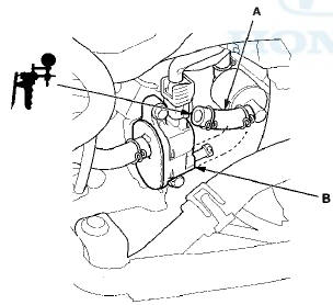
6. Disconnect the vacuum hose (A) from the purge valve (B) in the engine compartment, and connect a vacuum pump/gauge, 0-”30 in.Hg, to the hose.
7. Start the engine, and let it idle.
Is there vacuum? YES
-Go to step 8.
NO
-Go to step 14.
8. Turn the ignition switch to LOCK (0).
9. Disconnect the EVAP canister purge valve 2P connector.
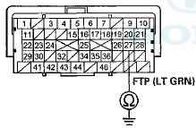
10. Check for continuity between EVAP canister purge valve 2P connector terminal No. 2 and body ground.
EVAP CANISTER PURGE VALVE 2P CONNECTOR
Wire side of female terminals
Is there continuity? YES
-Go to step 11.
NO
-Go to step 23.
11. Jump the SCS line with the HDS.
12. Disconnect ECM/PCM connector B (49P).
13. Check for continuity between EVAP canister purge valve 2P connector terminal No. 2 and body ground.
EVAP CANISTER PURGfc VALVE 2P CONNECTOR
Wire side of female terminals
Is there continuity? YES
-Repair short in the wire between the EVAP canister purge valve and the ECM/PCM (B3), then go to step 24.
NO
-Go to step 30.
14. Turn the ignition switch to LOCK (0).
15. Disconnect the EVAP canister purge valve 2P connector.
16. Turn the ignition switch to ON (II).
17. Measure the voltage between EVAP canister purge valve 2P connector terminal No. 1 and body ground.
EVAP CANISTER PURGE VALVE 2P CONNECTOR
Wire side of female terminals
Is there battery voltage? YES-
Go to step 18.
NO
-Repair open in the wire between the EVAP canister purge valve and the No. 7 ACG (15 A) fuse in the driver's under-dash fuse/relay box, then go to step 24.
18. Turn the ignition switch to LOCK (0).
19. Jump the SCS line with the HDS.
20. Disconnect ECM/PCM connector B (49P).
21. Check for continuity between ECM/PCM connector terminal B3 and EVAP canister purge valve 2P connector terminal No. 2.
EVAP CANISTER PURGE VALVE 2P CONNECTOR
Terminal side of female terminals
Is there continuity? YES
-Go to step 22.
NO
-Repair open in the wire between the EVAP canister purge valve and the ECM/PCM (B3), then go to step 24.
22. At the valve side, measure the resistance between EVAP canister purge valve 2P connector terminals No. 1 and No. 2.
EVAP CANISTER PURGE VALVE 2P CONNECTOR

Terminal side of male terminals
Is there about 23-”26 Q at room temperature? YES-
Go to step 30.
NO
-Go to step 23.
23. Replace the EVAP canister purge valve (see page 11-371).
24. Reconnect all connectors.
25. Turn the ignition switch to ON (II).
26. Reset the ECM/PCM with the HDS.
27. Do the ECM/PCM idle learn procedure (see page 11-293).
28. Check for Pending or Confirmed DTCs with the HDS.
Is DTC P0443 indicated? YES
-Check for poor connections or loose terminals at the EVAP canister purge valve and the ECM/PCM, then go to step 1.
NO
-Go to step 29.
29. Monitor the OBD STATUS for DTC P0443 in the DTCs MENU with the HDS.
Does the screen indicate PASSED? YES
-Troubleshooting is complete. If any other Pending or Confirmed DTCs were indicated in step 28, go to the indicated DTCs troubleshooting.
NO
-lf the screen indicates FAILED, check for poor connections or loose terminals at the EVAP canister purge valve and the ECM/PCM, then go to step 1. If the screen indicates EXECUTING, OUT OF CONDITION, or NOT COMPLETED, keep idling until a result comes on.
30. Reconnect all connectors.
31. Update the ECM/PCM if it does not have the latest software (see page 11 -203), or substitute a known-good ECM/PCM (see page 11-7).
32. Start the engine, and let it idle.
33. Check for Pending or Confirmed DTCs with the HDS.
Is DTC P0443 indicated?
YES
-Check for poor connections or loose terminals at the EVAP canister purge valve and the ECM/PCM. If the ECM/PCM was updated, substitute a known-good ECM/PCM (see page 11-7), then go to step 32. If the ECM/PCM was substituted, go to step 1.
NO
-Go to step 34.
34. Monitor the OBD STATUS for DTC P0443 in the DTCs MENU with the HDS.
Does the screen indicate PASSED? YES
-lf the ECM/PCM was updated, troubleshooting is complete. If the ECM/PCM was substituted, replace the original ECM/PCM (see page 11-204). If any other Pending or Confirmed DTCs were indicated in step 33, go to the indicated DTCs troubleshooting.
NO
-lf the screen indicates FAILED, check for poor connections or loose terminals at the EVAP canister purge valve and the ECM/PCM. If the ECM/PCM was updated, substitute a known-good ECM/PCM (see page 11-7), then go to step 32. If the ECM/PCM was substituted, go to step 1. If the screen indicates EXECUTING, OUT OF CONDITION, or NOT COMPLETED , keep idling until a result comes on.
DTC P0451:
FTP Sensor Circuit
Range/Performance Problem
NOTE: - Before you troubleshoot, record all freeze data and any on-board snapshot, and review the general troubleshooting information (see page 11-3).
- If DTC P2422 is stored at the same time as DTC P0451, troubleshoot DTC P2422 first, then recheck for DTC P0451.
1. Turn the ignition switch to ON (II).
2. Clear the DTC with the HDS.
3. Start the engine, and let it idle for 1 minute.
4. Monitor the OBD STATUS for DTC P0451 in the DTCs MENU with the HDS.
Does the screen indicate FAILED? YES
-Go to step 5.
NO
-lf the screen indicates PASSED, intermittent failure, the system is OK at this time. Check for poor connections or loose terminals at the FTP sensor and the ECM/PCM. If the screen indicates NOT COMPLETED, keep idling until a result comes on.
5. Turn the ignition switch to LOCK (0).
6. Replace the FTP sensor (see page 11-370).
7. Turn the ignition switch to ON (II).
8. Reset the ECM/PCM with the HDS.
9. Do the ECM/PCM idle learn procedure (see page 11-293).
10. Start the engine, and let it idle for 1 minute.
11. Check for Pending or Confirmed DTCs with the HDS.
Is DTC P0451 indicated?
YES
-Check for poor connections or loose terminals at the FTP sensor and the ECM/PCM, then go to step 1.
NO
-Go to step 12.
12. Monitor the OBD STATUS for DTC P0451 in the DTCs MENU with the HDS.
Does the screen indicate PASSED? YES
-Troubleshooting is complete. If any other Pending or Confirmed DTCs were indicated in step 11, go to the indicated DTCs troubleshooting.
NO
-lf the screen indicates FAILED, check for poor connections or loose terminals at the FTP sensor and the ECM/PCM, then go to step 1. If the screen indicates NOT COMPLETED, keep idling until a result comes on.
DTC P0452
: FTP Sensor Circuit Low Voltage
NOTE: Before you troubleshoot, record all freeze data and any on-board snapshot, and review the general troubleshooting information (see page 11-3).
1. Turn the ignition switch to ON (II).
2. Clear the DTC with the HDS.
3. Turn the ignition switch to LOCK (0).
4. Remove the fuel fill cap.
5. Turn the ignition switch to ON (II).
6. Check the FTP SENSOR in the DATA LIST with the HDS.
Is about -”7.3 kPa (-2.16 InHg, -55 mmHg), or 0.3 Vor less indicsted?
YES
-Go to step 10.
NO
-Go to step 7.
7. Install the fuel fill cap.
8. Start the engine.
9. Monitor the OBD STATUS for DTC P0452 in the DTCs MENU with the HDS.
Does the screen Indicate FAILED? YES
-Go to step 10.
NO
-lf the screen indicates PASSED, intermittent failure, the system is OK at this time. Check for poor connections or loose terminals at the FTP sensor and the ECM/PCM. If the screen indicates NOT COMPLETED, keep idling until a result comes on.
10. Turn the ignition switch to LOCK (0).
11. Disconnect the FTP sensor 3P connector.
12. Turn the ignition switch to ON (II).
13. Check the FTP SENSOR in the DATA LIST with the HDS.
Is about - 7.3 kPa (-2.16 inHg, -55 mmHg), or 0.3 Vor less indicated? YES
-Go to step 20.
NO
-Go to step 14.
14. Measure the voltage between FTP sensor 3P connector terminal No. 1 and body ground.
FTP SENSOR 3P CONNECTOR
Wire side of female terminals
Is there about 5 V? YES-Go to step 24.
NO-Go to step 15.
15. Turn the ignition switch to LOCK (0).
16. Jump the SCS line with the HDS.
17. Disconnect ECM/PCM connector A (49P).
18. Connect FTP sensor 3P connector terminal No. 1 to body ground with a jumper wire.
FTP SENSOR 3P CONNECTOR
Wire side of female terminals
19. Check for continuity between ECM/PCM connector terminal A20 and body ground.
ECM/PCM CONNECTOR A (49P)
Terminal side of female terminals
Is there continuity? YES
-Go to step 32.
NO
-Repair open in the wire between the ECM/PCM (A20) and the FTP sensor, then go to step 26.
20. Turn the ignition switch to LOCK (0).
21. Jump the SCS line with the HDS.
22. Disconnect ECM/PCM connector A (49P).
23. Check for continuity between FTP sensor 3P connector terminal No. 2 and body ground.
FTP SENSOR 3P CONNECTOR
Wire side of female terminals
Is there continuity? YES
-Repair short in the wire between the ECM/PCM (A27) and the FTP sensor, then go to step 26.
NO
-Go to step 32.
24. Turn the ignition switch to LOCK (0).
25. Replace the FTP sensor (see page 11-370).
26. Reconnect all connectors.
27. Turn the ignition switch to ON (II).
28. Reset the ECM/PCM with the HDS.
29. Do the ECM/PCM idle learn procedure (see page 11-293).
30. Check for Pending or Confirmed DTCs with the HDS.
Is DTC P0452 indicated? YES
-Check for poor connections or loose terminals at the FTP sensor and the ECM/PCM, then go to step 1.
NO
-Go to step 31.
31. Monitor the OBD STATUS for DTC P0452 in the DTCs MENU with the HDS.
Does the screen indicate PASSED? YES
-Troubleshooting is complete. If any other Pending or Confirmed DTCs were indicated in step 30, go to the indicated DTCs troubleshooting.
NO-lf the screen indicates FAILED, check for poor connections or loose terminals at the FTP sensor and the ECM/PCM, then go to step 1. If the screen indicates NOT COMPLETED, keep idling until a result comes on.
32. Reconnect all connectors.
33. Update the ECM/PCM if it does not have the latest software (see page 11-203), or substitute a known-good ECM/PCM (see page 11-7).
34. Start the engine, and let it idle.
35. Check for Pending or Confirmed DTCs with the HDS.
is DTC P0452 indicated?
Is DTC P0452 indicated? YES
-Check for poor connections or loose terminals at the FTP sensor and the ECM/PCM. If the ECM/PCM was updated, substitute a known-good ECM/PCM (see page 11-7), then go to step 34. If the ECM/PCM was substituted, go to step 1.
NO
-Go to step 36.
36. Monitor the OBD STATUS for DTC P0452 In the DTCs MENU with the HDS.
Does the screen indicate PASSED? YES
-lf the ECM/PCM was updated, troubleshooting is complete. If the ECM/PCM was substituted, replace the original ECM/PCM (see page 11-204). If any other Pending or Confirmed DTCs were indicated in step 35, go to the indicated DTCs troubleshooting.
NO
-lf the screen indicates FAILED, check for poor connections or loose terminals at the FTP sensor and the ECM/PCM. If the ECM/PCM was updated, substitute a known-good ECM/PCM (see page 11-7), then go to step 34. If the ECM/PCM was substituted, go to step 1. if the screen indicates NOT COMPLETED, keep idling until a result comes on.
DTC P0453:
FTP Sensor Circuit High Voltage
NOTE: Before you troubleshoot, record all freeze data and any on-board snapshot, and review the general troubleshooting information (see page 11-3).
1. Turn the ignition switch to ON (II).
2. Clear the DTC with the HDS.
3. Turn the ignition switch to LOCK (0).
4. Remove the fuel fill cap.
5. Turn the ignition switch to ON (II).
6. Check the FTP SENSOR in the DATA LIST with the HDS.
is about 7.3 kPa (2.16 inHg, 55 mmHg), or 4.7 V or more indicated? YES
-Go to step 10.
NO
-Go to step 7.
7. Install the fuel fill cap.
8. Start the engine.
9. Monitor the OBD STATUS for DTC P0453 in the DTCs MENU with the HDS.
Does the screen indicate FAILED? YES
-Go to step 10.
NO
-lf the screen indicates PASSED, intermittent failure, the system is OK at this time. Check for poor connections or loose terminals at the FTP sensor and the ECM/PCM. If the screen indicates NOT COMPLETED, keep idling until a result comes on.
10. Turn the ignition switch to LOCK (0).
11. Disconnect the FTP sensor 3P connector.
12. Connect FTP sensor 3P connector terminals No. 2 and No. 3 with a jumper wire.
FTP SENSOR 3P CONNECTOR
Wire side of female terminals
13. Turn the ignition switch to ON (II).
14. Check the FTP SENSOR in the DATA LIST with the .
HDS.
Is about 7.3 kPa (2.16 InHg, 55 mmHg), or 4.7 Vor more indicated? YES-Go to step 15.
NO-Go to step 26.
15. Measure the voltage between FTP sensor 3P connector terminals No. 1 and No. 3.
FTP SENSOR 3P CONNECTOR
Wire side of female terminals
Is there about 5 V? YES
-Go to step 21.
NO
-Go to step 16.
16. Turn the ignition switch to LOCK (0).
17. Jump the SCS line with the HDS.
18. Disconnect ECM/PCM connector A (49P).
19. Connect FTP sensor 3P connector terminal No. 3 to body ground with a jumper wire.
FTP SENSOR 3P CONNECTOR
Wire side of female terminals
20. Check for continuity between ECM/PCM connector terminal A10 and body ground.
ECM/PCM CONNECTOR A (49P)
Terminal side of female terminals
Is there continuity? YES
-Go to step 34.
NO-
Repair open in the wire between the ECM/PCM (A10) and the FTP sensor, then go to step 28.
21. Turn the ignition switch to LOCK (0).
22. Jump the SCS line with the HDS.
23. Disconnect ECM/PCM connector A (49P).
24. Connect FTP sensor 3P connector terminal No. 2 to body ground with a jumper wire.
FTP SENSOR 3P CONNECTOR
Wire side of female terminals
25. Check for continuity between ECM/PCM connector terminal A27 and body ground.
ECM/PCM CONNECTOR A (49P)
Terminal side of female terminals
Is there continuity? YES
-Go to step 34.
NO-
Repair open in the wire between the ECM/PCM (A27) and the FTP sensor, then go to step 28.
26. Turn the ignition switch to LOCK (0).
27. Replace the FTP sensor (see page 11-370).
28. Reconnect all connectors.
29. Turn the ignition switch to ON (II).
30. Reset the ECM/PCM with the HDS.
31. Do the ECM/PCM idle learn procedure (see page 11-293).
32. Check for Pending or Confirmed DTCs with the HDS.
Is DTC P0453 indicated? YES
-Check for poor connections or loose terminals at the FTP sensor and the ECM/PCM, then go to step 1.
NO
-Go to step 33.
33. Monitor the OBD STATUS for DTC P0453 in the DTCs MENU with the HDS.
Does the screen indicate PASSED? YES
-Troubleshooting is complete. If any other Pending or Confirmed DTCs were indicated in step 32, go to the indicated DTCs troubleshooting.
NO
-lf the screen indicates FAILED, check for poor connections or loose terminals at the FTP sensor and the ECM/PCM, then go to step 1. If the screen indicates NOT COMPLETED, keep idling until a result comes on.
34. Reconnect all connectors.
35. Update the ECM/PCM if it does not have the latest software (see page 11-203), or substitute a known-good ECM/PCM (see page 11-7).
36. Start the engine, and let it idle.
37. Check for Pending or Confirmed DTCs with the HDS.
Is DTC P0453 indicated? YES
-Check for poor connections or loose terminals at the FTP sensor and the ECM/PCM. If the ECM/PCM was updated, substitute a known-good ECM/PCM (see page 11-7), then go to step 36. If the ECM/PCM was substituted, go to step 1.
NO
-Go to step 38.
38. Monitor the OBD STATUS for DTC P0453 in the DTCs MENU with the HDS.
Does the screen indicate PASSED? YES
-lf the ECM/PCM was updated, troubleshooting is complete. If the ECM/PCM was substituted, replace the original ECM/PCM (see page 11-204). If any other Pending or Confirmed DTCs were indicated in step 37, go to the indicated DTCs troubleshooting.
NO
-lf the screen indicates FAILED, check for poor connections or loose terminals at the FTP sensor and the ECM/PCM. If the ECM/PCM was updated, substitute a known-good ECM/PCM (see page 11-7), then go to step 36. If the ECM/PCM was substituted, go to step 1. If the screen indicates NOT COMPLETED, keep idling until a result comes on.
DTC P0455:
EVAP System Large Leak Detected
DTC P0456:
EVAP System Very Small Leak Detected
NOTICE
The fuel system is designed to allow specified maximum vacuum and pressure conditions. Do not deviate from the vacuum and pressure tests as indicated in these procedures. Excessive pressure/vacuum would damage the EVAP components or cause eventual fuel tank failure.
Special Tools Required
Vacuum Pump/Gauge, 0 - 3 0 in.Hg, Snap-on YA4000A or equivalent, commercially available
NOTE: - Before you troubleshoot, record all freeze data and any on-board snapshot, and review the general troubleshooting information (see page 11-3).
- Fresh fuel has a higher volatility that will create greater pressure/vacuum. The best condition for testing is less than a full tank of fresh fuel. If possible, to assist in leak detection, add 1 gallon of fresh fuel to the tank (as long as it will not fill the tank), just before starting these procedures.
1. Check the fuel fill cap (the cap must say TIGHTEN TO CLICK). It should turn 1/4 turn after it's tight, then it clicks.
Is the correct fuel fill cap installed and properly tightened? YES-Go to step 2.
NO-Replace or tighten the cap, then go to step 29.
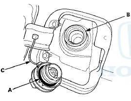
2. Check the fuel fill cap seal (A) and the fuel fill pipe mating surface (B). Verify that the fuel fill cap tether cord (C) is not caught under the cap.
Is the fuel fill cap seal missing or damaged, Is the fuel fill pipe damaged, or Is the tether cord caught under the cap? YES
-Replace the fuel fill cap or the fuel fill pipe, then go to step 29.
NO
-Go to step 3.
3. Turn the ignition switch to ON (II).
4. Clear the DTC with the HDS.
5. Do the EVAP FUNCTION TEST in the INSPECTION MENU with the HDS.
Is the result OK? YES
-lntermittent failure, the system is OK at this time.
Check for poor connections or loose terminals at the FTP sensor, the EVAP canister purge valve, or the EVAP canister vent shut valve, and the ECM/PCM.B NO
-Go to step 6.
6. Turn the ignition switch to LOCK (0).
7 Check for a poor connection or damage at the fuel tank vapor recirculation tube.
Is the tube OK? YES-
Go to step 8.
NO-
- Replace the fuel tank vapor recirculation tube, then go to step 29.
- If necessary, replace the fuel tank (see page 11 -325), then go to step 29.
8. Disconnect the fuel tank vapor recirculation tube (A) and fresh air hose (B) from the EVAP canister (C), and plug the EVAP canister port (D).
9. Disconnect the vacuum hose (engine side) (A) from the EVAP canister purge valve (B) in the engine compartment, and connect a vacuum pump/gauge, 0-”30 in.Hg, to the purge valve as shown.
10. Turn the ignition switch to ON (II).
11. Select EVAP PCS ON in the INSPECTION MENU with the HDS.
12. Apply vacuum to the hose until the FTP reads 1.90 V (-0.59 inHg, -15.1 mmHg).
NOTE: Be careful not to exceed the vacuum. If you do, the FTP sensor can be damaged.
13. Select EVAP PCS OFF in the INSPECTION MENU with the HDS, and disconnect the vacuum pump/gauge.
14. Monitor the FTP SENSOR in the DATA LIST for 1 minute with the HDS.
Does the voltage increase more than 0.2 V (0.1 inHg, 2.5 mmHg)? YES
-Go to step 15.
NO
-Go to step 20.
15. Reconnect the vacuum hose (engine side) to the EVAP canister purge valve.
16. Disconnect the vacuum hose (EVAP canister side) (A) from the EVAP canister purge valve (B) in the engine compartment, and connect the vacuum pump/gauge to the vacuum hose as shown.
17. Apply vacuum to the hose until the FTP reads 1.90 V (-0.59 inHg, -”15.1 mmHg).
NOTE: Be careful not to exceed the vacuum. If you do, the FTP sensor can be damaged.
18. Monitor the FTP SENSOR in the DATA LIST for I minute with the HDS.
Does the voltage increase more than 0.2 V (0.1 inHg, 2.5 mmHg)? YES
-Go to step 19.
NO
-Replace the EVAP canister purge valve (see page I I -371), then go to step 28.
19. Check for a loose or damaged EVAP canister purge line between the EVAP canister and the EVAP canister purge valve, or a leaking EVAP canister.
Are the line and the EVAP canister OK? YES
-Replace these parts, then go to step 28:
- FTP sensor O-ring
- EVAP canister vent shut valve O-ring
- EVAP canister
NO
-Reconnect or repair the EVAP canister purge line, then go to step 28.
20. Reconnect the fresh air hose (A) to the EVAP canister (B).
21. Reconnect the vacuum hose (engine side) t o the EVAP canister purge valve.
22. Disconnect the vacuum hose (EVAP canister side) (A) from the EVAP canister purge valve (B) in the engine compartment, and connect the vacuum pump/gauge to the vacuum hose as shown.
23. Select EVAP CVS ON in the INSPECTION MENU with the HDS.
24. Apply vacuum to the hose until the FTP reads 1.90 V (-0.59 inHg, -15.1 mmHg).
NOTE: Be careful not to exceed the vacuum. If you do, the FTP sensor can be damaged.
25. Monitor the FTP SENSOR in the DATA LIST for 1 minute with the HDS.
Does the voltage increase more than 0.2 V (0.1 inHg, 2.5 mmHg)? YES-Replace the EVAP canister vent shut valve (see page 11-371), then go to step 28.
NO-Go to step 26.
26. Select EVAP CVS OFF in the INSPECTION MENU with the HDS.
27. Check these parts for looseness or damage:
- Fuel fill pipe
- Fuel vapor return pipe
Are the parts OK? YES
-Check the fuel tank unit base gasket (see page 11-321), and check the fuel tank, then go to step 28.
NO-
Repair or replace the damaged parts, then go to step 28.
28. Reconnect all hoses and connectors.
29. Turn the ignition switch to ON (II).
30. Reset the ECM/PCM with the HDS.
31. Do the ECM/PCM idle learn procedure (see page 11-293).
32. Do the EVAP FUNCTION TEST in the INSPECTION MENU with the HDS.
Is the result OK? YES-
Troubleshooting is complete.
NO
-Check for poor connections or loose terminals at the FTP sensor, the EVAP canister purge valve, the EVAP canister vent shut valve, and the ECM/PCM, then go to step 1.
DTC P0457:
EVAP System Leak Detected/Fuel Fill Cap Loose or Missing
NOTE: Before you troubleshoot, record all freeze data and any on-board snapshot, and review the general troubleshooting information (see page 11-3).
1. Check the fuel fill cap (the cap must say TIGHTEN TO CLICK). It should turn 1/4 turn after it's tight, then it clicks.
Is the correct fuel fill cap installed and properly tightened? YES
-Go to step 2.
NO
-Replace or tighten the cap, then go to step 19.
2. Check the fuel fill cap seal (A) and the fuel fill pipe mating surface (B). Verify that the fuel fill cap tether cord (C) is not caught under the cap.
Is the fuel fill cap seal missing or damaged, is the fuel fill pipe damaged, or is the tether cord caught under the cap? YES
-Replace the fuel fill cap or the fuel fill pipe, then goto step 19.
NO
-Go to step 3.
3. Turn the ignition switch to ON (II).
4. Clear the DTC with the HDS.
5. Do the EVAP FUNCTION TEST in the INSPECTION MENU with the HDS.
Is the result OK? YES
-lntermittent failure, the system is OK at this time.
Check for poor connections or loose terminals at the FTP sensor or the EVAP canister vent shut valve and the ECM/PCM.B NO
-Go to step 6.
6. Turn the ignition switch to LOCK (0).
7. Remove the EVAP canister vent shut valve from the EVAP canister (see page 11-371).
8. Connect the 2P connector to the EVAP canister vent shut valve.
9. Turn the ignition switch to ON (II).
10. Select EVAP CVS ON in the INSPECTION MENU with the HDS.
11. Check the EVAP canister vent shut valve (A) operation.
Does the valve operate? YES
-Check the routing of the EVAP canister vent tube, then go to step 18.
NO
-Go to step 12.
12. Turn the ignition switch to LOCK (0).
13. Replace the EVAP canister vent shut valve (see page 11-371).
14. Turn the ignition switch to ON (II).
15. Reset the ECM/PCM with the HDS.
16. Do the ECM/PCM idle learn procedure (see page 11-293).
17. Do the EVAP FUNCTION TEST in the INSPECTION MENU with the HDS.
Is the result OK? YES
-Troubleshooting is complete.
NO
-Check for poor connections or loose terminals at the FTP sensor, then go to step 1.
18. Reinstall the EVAP canister vent shut valve.
19. Turn the ignition switch to ON (II).
20. Reset the ECM/PCM with the HDS.
21. Do the ECM/PCM idle learn procedure (see page 11-293).
22. Do the EVAP FUNCTION TEST in the INSPECTION MENU with the HDS.
Is the result OK? YES
-Troubleshooting is complete.
NO-
Check for poor connections or loose terminals at the FTP sensor, the EVAP canister vent shut valve, and the ECM/PCM, then go to step 1.
DTC P0496:
EVAP System High Purge Flow Detected
NOTE: Before you troubleshoot, record all freeze data and any on-board snapshot, and review the general troubleshooting information (see page 11-3).
1. Turn the ignition switch to ON (II).
2. Clear the DTC with the HDS.
3. Do the EVAP FUNCTION TEST in the INSPECTION MENU with the HDS.
Is the result OK? YES
-lntermittent failure, the system is OK at this time.
Check for poor connections or loose terminals at the FTP sensor, the EVAP canister purge valve.-th* R'AP canister vent shut valve, and the ECM/PCM.
NO
-Go to step 4.
4. Turn the ignition switch to LOCK (0).
5. Replace the EVAP canister purge valve (see page 11-371).
6. Turn the ignition switch to ON (II).
7. Reset the ECM/PCM with the HDS.
8. Do the ECM/PCM idle learn procedure (see page 11-293).
9. Do the EVAP FUNCTION TEST in the INSPECTION MENU with the HDS.
Is the result OK? YES
-Troubleshooting is complete.
NO
-Check for poor connections or loose terminals at the FTP sensor, the EVAP canister purge valve, the EVAP canister vent shut valve, and the ECM/PCM, then go to step 1.
DTC P0497:
EVAP System Low Purge Flow Detected
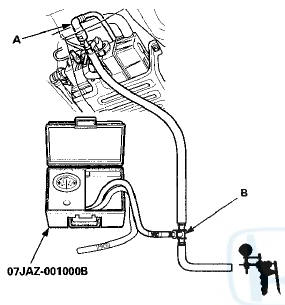
Special Tools Required
- Vacuum/Pressure Gauge, 0-”4 In.Hg, 07JAZ-001000B
- Vacuum Pump/Gauge, 0 - 3 0 In.Hg, Snap-on YA4000A or equivalent, commercially available
NOTE: Before you troubleshoot, record all freeze data and any on-board snapshot, and review the general troubleshooting information (see page 11-3).
1. Turn the ignition switch to ON (II).
2. Clear the DTC with the HDS.
3. Do the EVAP FUNCTION TEST in the INSPECTION MENU with the HDS.
Is the result OK? YES
-lntermittent failure, the system is OK at this time.
Check for poor connections or loose terminals at the EVAP canister purge valve, the FTP sensor, and the ECM/PCM.
NO
-Go to step 4.
4. Turn the ignition switch to LOCK (0).
5. Check for poor connections, blockage, or damage in the EVAP canister purge line between the throttle body and the EVAP canister.
Is the line OK? YES-
Go to step 6.
NO
-Reconnect or repair the EVAP canister purge line, then go to step 24.
6. Disconnect the vacuum hose (A) from the EVAP canister purge valve (B).
7. Disconnect the vacuum hose (A) from the purge line (at the EVAP canister side), then connect a T-fitting (B), a vacuum gauge, and a vacuum pump/gauge, 0-”30 in.Hg, to the hose as shown.
8. Turn the ignition switch to ON (II).
9. Apply about 2 kPa (0.6 inHg, 15 mmHg) of vacuum to the hose.
10. Select EVAP PCS ON in the INSPECTION MENU with the HDS.
Does the vacuum release immediately? YES-Go to step 15.
NO-Go to step 11.
11. Select EVAP PCS OFF in the INSPECTION MENU with the HDS.
12. Disconnect the vacuum hose (A) from the EVAP canister purge valve (B). Connect a T-fitting (C), the vacuum gauge, and the vacuum pump/gauge to the EVAP canister purge valve as shown.
13. Apply about 2 kPa (0.6 inHg, 15 mmHg) of vacuum to the hose.
14. Select EVAP PCS ON in the INSPECTION MENU with the HDS.
Does the vacuum release immediately? YES-Check for a blockage in the EVAP canister purge line between the EVAP canister purge valve and the EVAP canister, then go to step 24.
NO-Replace the EVAP canister purge valve (see page 11-371), then go to step 24.
15. Connect the vacuum pump/gauge to the vacuum hose (A) as shown.
16. Start the engine, and let it idle.
Is there vacuum? YES-Go to step 17.
NO-Check for a blockage at the EVAP purge line between the throttle body and the EVAP canister purge valve, then go to step 24.
17. Turn the ignition switch to LOCK (0).
18. Remove the FTP sensor with its connector connected (see page 11-370).
19. Connect a T-fitting (A) to the vacuum pump/gauge, then connect the vacuum pump to the FTP sensor (B) as shown.
20. Turn the ignition switch to ON (II).
21. Check and record the FTP SENSOR reading in the DATA LIST with the HDS.
22. Slowly apply about 1.3 kPa (0.4 inHg, 10 mmHg) of vacuum to the hose.
23. Check the FTP SENSOR in the DATA LIST with the HDS.
Does the value change? YES
-Check for debris or blockage at the EVAP canister port, then go to step 24.
NO
-Replace the FTP sensor (see page 11-370), then go to step 24.
24. Turn the ignition switch to ON (II).
25. Reset the ECM/PCM with the HDS.
26. Do the ECM/PCM idle learn procedure (see page 11-293).
27. Do the EVAP FUNCTION TEST in the INSPECTION MENU with the HDS.
Is the result OK? YES
-Troubleshooting is complete.il NO
-Check for poor connections or loose terminals at the EVAP canister purge valve, the FTP sensor, and the ECM/PCM, then go to step 1.
i^p; D4S8:
EVAP Canister Vent Shut Valve Circuit Low Voltage
NOTE: Before you troubleshoot,. record all freeze data and any on-board snapshot, and review the general troubleshooting information (see page 11-3).
1. Turn the ignition switch to ON (ll).
2. Clear the DTC with the HDS.
3. Check for Pending or Confirmed DTCs with the HDS.
Is DTC P0498 indicated? YES
-Go to step 6.
NO-
Go to s t e p 4.
4. Select EVAP CVS ON in the INSPECTION MENU with the HDS.
5. Check for Pending or Confirmed DTCs with the HDS.
Is DTC P0498 indicated? YES
-Go to step 6.
NO
-lntermittent failure, the system is OK at this time.
Cneck for poor connections or loose terminals at the EVAP canister vent shut valve and the ECM/PCM.
6. Turn the ignition switch to LOCK (0).
7. Disconnect the EVAP canister vent shut valve 2P connector.
8. Turn the ignition switch to ON (ll).
9. Measure the voltage between EVAP canister vent shut valve 2P connector terminal No. 2 and body ground.
EVAP CANISTER VENT SHUT VALVE 2P CONNECTOR
Wire side of female terminals
Is there battery voltage? YES
-Go to step 10.
NO
-Repair open in the wire between the EVAP canister vent shut valve and the PGM-FI subrelay, then go to step 18.
10. Turn the ignition switch to LOCK (0).
11. At the valve side, measure the resistance between EVAP canister vent shut valve 2P connector terminals No. 1 and No. 2.
EVAP CANISTER VENT SHUT VALVE 2P CONNECTOR
Terminal side of male terminals
Is there about 25-”30 0 at room temperature? YES
-Go to step 12.
NO
-Go to step 17.
12. Jump the SCS line with the HDS.
13. Disconnect ECM/PCM connector A (49P).
14. Check for continuity between ECM/PCM connector terminal A11 and body ground.
ECM/PCM CONNECTOR A (49P)
Terminal side of female terminals
Is there continuity? YES
-Repair short in the wire between the EVAP canister vent shut valve and the ECM/PCM (A11), then go to step 18.
NO
-Go to step 15.
15. Connect EVAP canister vent shut valve 2P connector terminal No. 1 to body ground with a jumper wire.
EVAP CANISTER VENT SHUT VALVE 2P CONNECTOR
Wire side of female terminals
16. Check for continuity between ECM/PCM connector terminal A11 and body ground.
ECM/PCM CONNECTOR A (49P)
Terminal side of female terminals
Is there continuity? YES
-Go to step 25.
NO
-Repair open in the wire between the EVAP canister vent shut valve and the ECM/PCM (A11), then goto step 18.
17. Replace the EVAP canister vent shut valve (see page 11-371).
18. Reconnect all connectors.
19. Turn the ignition switch to ON (II).
20. Reset the ECM/PCM with the HDS.
21. Do the ECM/PCM idle learn procedure (see page 11-293).
22. Select EVAP CVS ON in the INSPECTION MENU with the HDS.
23. Check for Pending or Confirmed DTCs with the HDS.
Is DTC P0498 indicated? YES
-Check for poor connections or loose terminals at the EVAP canister vent shut valve and the ECM/PCM, then go to step 1.
NO
-Go to step 24.
24. Monitor the OBD STATUS for DTC P0498 in the DTCs MENU with the HDS.
Does the screen indicate PASSED? YES
-Troubleshooting is complete. If any other Pending or Confirmed DTCs were indicated in step 23, go to the indicated DTCs troubleshooting.
NO
-lf the screen indicates FAILED, check for poor connections or loose terminals at the EVAP canister vent shut valve and the ECM/PCM, then go to step 1. If the screen indicates NOT COMPLETED, go to step 22.
25. Reconnect all connectors.
26. Update the ECM/PCM if it does not have the latest software (see page 11-203), or substitute a known-good ECM/PCM (see page 11-7).
27. Select EVAP CVS ON in the INSPECTION MENU with the HDS.
28. Check for Pending or Confirmed DTCs with the HDS.
is DTC P0498 indicated? YES
-Check for poor connections or loose terminals.at the EVAP canister vent shut valve and the ECM/PCM.
If the ECM/PCM was updated, substitute a known-good ECM/PCM (see page 11 -7), then go to step 27. If the ECM/PCM was substituted, go to step 1.
NO
-Go to step 29.
29. Monitor the OBD STATUS for DTC P0498 in the DTCs MENU with the HDS.
Does the screen indicate PASSED? YES
-lf the ECM/PCM was updated, troubleshooting is complete. If the ECM/PCM was substituted, replace the original ECM/PCM (see page 11-204). If any other Pending or Confirmed DTCs were indicated in step 28, go to the indicated DTCs troubleshooting.
NO
-lf the screen indicates FAILED, check for poor connections or loose terminals at the EVAP canister vent shut valve and the ECM/PCM. If the ECM/PCM was updated, substitute a known-good ECM/PCM (see page 11-7), then go to step 27. If the ECM/PCM was substituted, go to step 1. If the screen indicates NOT COMPLETED, go to step 27.
DTC P0499:
EVAP Canister Vent Shut Valve Circuit High Voltage
NOTE: Before you troubleshoot, record all freeze data and any on-board snapshot, and review the general troubleshooting information (see page 11-3).
1. Turn the ignition switch to ON (II).
2. Clear the DTC with the HDS.
3. Select EVAP CVS ON in the INSPECTION MENU with the HDS.
4. Check for Pending or Confirmed DTCs with the HDS.
Is DTC P0499 indicated? YES
-Go to step 5.
NO
-lntermittent failure, the system is OK at this time.
Check for poor connections or loose terminals at the EVAP canister vent shut valve and the ECM/PCM.- 5. Update the ECM/PCM if it does not have the latest software (see page 11-203), or substitute a known-good ECM/PCM (see page 11-7).
6. Select EVAP CVS ON in the INSPECTION MENU with the HDS.
7. Check for Pending or Confirmed DTCs with the HDS.
Is DTC P0499 indicated? YES
-Check for poor connections or loose terminals at the EVAP canister vent shut valve and the ECM/PCM.
If the ECM/PCM was updated, substitute a known-good ECM/PCM (see page 11-7), then go to step 6. If the ECM/PCM was substituted, go to step 1.
NO
-Go to step 8.
8. Monitor the OBD STATUS for DTC P0499 in the DTCs MENU with the HDS.
Does the screen indicate PASSED?
YES
-lf the ECM/PCM was updated, troubleshooting is complete. If the ECM/PCM was substituted, replace the original ECM/PCM (see page 11-204). If any other Pending or Confirmed DTCs were indicated in step 7, go to the indicated DTCs troubleshooting.
NO
-lf the screen indicates FAILED, check for poor connections or loose terminals at the EVAP canister vent shut valve and the ECM/PCM. If the ECM/PCM was updated, substitute a known-good ECM/PCM (see page 11-7), then go to step 6. If the ECM/PCM was substituted, go to step 1. If the screen indicates NOT COMPLETED, go to step 6.
DTC P14S4:
FTP Sensor Range/Performance Problem
DTC P2422
; EVAP Canister Vent Shut Valve Stuck Closed Malfunction
N O T E : Before you troubleshoot record all freeze data and any on-board snapshot and review the general troubleshooting information {see page 11-3).
1. Turn the ignition switch to ON (II).
2. Clear the DTC with the HDS.
3. Turn the ignition switch to LOCK (0).
4. Remove the fuel fill cap, and wait 1 minute.
5. Turn the ignition switch to ON (II).
6. Check the FTP SENSOR in the DATA LIST with the HDS.
Is it between -0.67 and 0.67 kPa (-0.2 and 0.2 inHg, - 5 and 5 mmHg), or 2.4 and 2.6 V? YES
-Go to step 7.
NO
-Go to step 18.
7. Install the fuel fill cap.
8. Clear the DTC with the HDS.
9. Start the engine. Hold the engine speed at 3,000 rpm without load (A/T in P or N, M/T in neutral) until the radiator fan comes on, then let it idle.
10. Monitor the OBD STATUS for DTC P1454 in the DTCs MENU with the HDS.
Does the screen indicate FAILED? YES
-Go to step 11.
NO
-lf the screen indicates PASSED, intermittent failure, the system is OK at this time. Check for poor connections or loose terminals at the FTP sensor, the EVAP canister vent shut valve, and the ECM/PCM.
Also check for a blockage in the vent hoses and the drain joint. If the screen indicates NOT COMPLETED, keep idling until a result comes on.
11. Clear the DTC with the HDS.
12. Turn the ignition switch to LOCK (0).
13. Remove the EVAP canister vent shut valve from the EVAP canister (see page 11-371).
14. Connect the 2P connector to the EVAP canister vent shut valve.
15. Turn the ignition switch to ON (II).
16. Select EVAP CVS ON in the INSPECTION MENU with the HDS.
17. Check the EVAP canister vent shut valve (A) operation.
Does the valve operate? YES
-Check for a blockage in the EVAP canister, vent hoses, and drain joint, then reinstall the EVAP canister vent shut valve, and go to step 24.
NO
-Replace the EVAP canister vent shut valve (see page 11-371), then go to step 24.
18. Disconnect the air tube (A) from the FTP sensor (B).
19. Check the FTP SENSOR in the DATA LIST with the HDS.
Is it between -0.67 and 0.67 kPa (-0.2 and 0.2 inHg, - 5 and 5 mmHg), or 2.4 and 2.6 V? YES
-Check for a blockage in the FTP sensor air tube or vent, then go to step 24.
NO
-Go to step 20.
20. Turn the ignition switch to LOCK (0).
21. Remove the FTP sensor (A) from the EVAP canister with its connector connected (see page 11-370).
22. Turn the ignition switch to ON (II).
23. Check the FTP SENSOR in the DATA LIST with the HDS.
Is it between -”0.67 kPa and 0.67 kPa (-”0.2 and 0.2 inHg, -5 and 5 mmHg), or 2.4 and 2.6 V? YES
-Check for debris or clogging at the EVAP canister and the FTP sensor port, then go to step 24.
NO
-Replace the FTP sensor (see page 11-370), then go to step 24.
24. Turn the ignition switch to ON (II).
25. Reset the ECM/PCM with the HDS.
26. Do the ECM/PCM idle learn procedure (see page 11-293).
27. Check for Pending or Confirmed DTCs with the HDS.
Is DTC P1454 and/or P2422 indicated? YES-
Check for poor connections or loose terminals at the FTP sensor, the EVAP canister vent shut valve, and the ECM/PCM, then go to step 1.
NO
-Go to step 28.
28. Monitor the OBD STATUS for DTC P1454 in the DTCs MENU with the HDS.
Does the screen indicate PASSED? YES
-Troubleshooting is complete. If any other Pending or Confirmed DTCs were indicated in step 27, go to the indicated DTCs troubleshooting.
NO
-lf the screen indicates FAILED, check for poor connections or loose terminals at the FTP sensor, the EVAP canister vent shut valve, and the ECM/PCM, then go to step 1. If the screen indicates NOT COMPLETED, keep idling until a result comes on.
DTC P14SC:
EVAP System Purge Flow Malfunction
NOTE; - Before you troubleshoot, record all freeze data and any on-board snapshot, and review the general troubleshooting information (see page 11-3).
- If DTC P145C is indicated alone, do the troubleshooting for DTC P0496 and P0497 using freeze data for P145C.
- If DTC P0497 and P145C are stored at the same time, check for a poor connection, a blockage, or damage at the EVAP canister purge line between the EVAP canister purge valve and the EVAP canister. Also check for a stuck closed EVAP canister purge valve.
- If any of the DTCs listed below are indicated at the same time as DTC P145C, troubleshoot those DTCs first, then recheck for P145C.
P0496, P0497: EVAP system purge flow

 Fuel Cap Warning Message System
Troubleshooting
Fuel Cap Warning Message System
Troubleshooting
Special Tools Required
- Vacuum Pump/Gauge, 0 - 3 0 In.Hg, Snap-on YA4000A
or equivalent, commercially available
- Vacuum/Pressure Gauge, 0 - 4 In.Hg, 07JAZ-001000B
comes on frequently, or if the ...
See also:
Brake System
• Parking Brake
Use the parking brake to keep the vehicle stationary when parking.
To apply:
Pull the lever fully up without pressing the
release button.
To release:
1. Pull the lever sli ...
Cooling System
Component Location Index
Radiator Cap Test
1. Wait until the engine is cool, then carefully remove
the radiator cap (A). Wet the radiator cap seal with
engine coolant, then install it on a com ...
Dual Temperature Control
Your vehicle has two temperature
control switches, one for the driver,
and one for the front passenger.
The temperatures of the driver’s side
and the front passenger’s side are
controlled ...