 Honda Accord: DTC Troubleshooting
DTC P0461:
Fuel Level Sensor (Fuel Gauge Sending Unit) Circuit Range/Performance Problem
NOTE: - Before you troubleshoot record all freeze data and any on-board snapshot, and review the general troubleshooting information (see page 11-3).
- Because it requires 162 miles (260 km) of driving without refueling to complete this diagnosis, DTC P0461 cannot be duplicated during this troubleshooting.
1. Test the fuel gauge sending unit (see page 11 -328).
Is the fuel gauge sending unit OK? YES
-Check for poor connections or loose terminals at the fuel gauge sending unit and the gauge control module.
NO
-Replace the fuel gauge sending unit (see page 11-324), then go to step 2.
2. Turn the ignition switch to ON (II).
3. Reset the ECM/PCM with the HDS.
4. Do the ECM/PCM idle learn procedure (see page 11-293).
5. Check for Pending or Confirmed DTCs with the HDS.
Are any Pending or Confirmed DTCs indicated? YES-Go to the indicated DTCs troubleshooting.
NO
-Troubleshooting is complete
DTC P0462:
Fuel Level Sensor (Fuel Gauge Sending Unit) Circuit Low Voltage
NOTE: Before you troubleshoot, record all freeze data and any on-board snapshot, and review the general troubleshooting information (see page 11-3).
1. Turn the ignition switch to ON (II).
2. Clear the DTC with the HDS, and wait 5 seconds.
3. Check for Pending or Confirmed DTCs with the HDS.
Is DTC P0462 indicated? YES
-Go to step 4.
NO
-lntermittent failure, the system is OK at this time.
Check for poor connections or loose terminals at the cetsgc centre! module arid the fuel gauge sending unit.
4. Turn the ignition switch to LOCK (0).
5. Remove the rear seat cushion (see page 20-241).
6. Remove the access panel from the floor (see page 11-320).
7. Disconnect the fuel tank unit 4P connector.
8. Turn the ignition switch to ON (II).
9. Clear the DTC with the HDS, and wait 5 seconds.
10. Check for Pending or Confirmed DTCs with the HDS.
Is DTC P0463 indicated? YES
-Replace the fuel gauge sending unit (see page 11-324), then go to step 23.
NO
-Go to step 11.
11. Measure the voltage between fuel tank unit 4P connector terminal No. 1 and body ground.
HJfcL TANK UNIT 4P CONNECTOR
Wire side of female terminals
Is there battery voltage? YES
-Go to step 16.
NO
-Go to step 12.
12. Turn the ignition switch to LOCK (0).
13. Remove the gauge control module (see page 22-351).
14. Disconnect the gauge control module 32P connector.
15. Check for continuity between fuel tank unit 4P connector terminal No. 1 and body ground.
FUEL TANK UNIT 4P CONNECTOR
Wire side of female terminals
Is there continuity? YES
-Repair short in the wire between the gauge control module (signal line) and the fuel gauge sending unit, then go to step 24.
NO
-Replace the gauge control module (see page 22-351), then go to step 24.
16. Turn the ignition switch to LOCK (0).
17. Remove the fuel tank unit (see page 11-320).
18. Connect the fuel tank unit 4P connector.
19. Turn the ignition switch to ON (II).
20. Clear the DTC with the HDS.
21. Set the float (A) to the E position.
22. Check the fuel gauge.
Does the gauge move to the empty position? YES
-Go to step 30.
NO
-Replace the gauge control module (see page 22-351), then go to step 23.
23. Turn the ignition switch to LOCK (0).
24. Reconnect all connectors.
25. Reinstall all removed parts in the reverse order of removal.
26. Turn the ignition switch to ON (II).
27. Reset the ECM/PCM with the HDS.
28. Do the ECM/PCM idle learn procedure (see page 11-293).
29. Check for Pending or Confirmed DTCs with the HDS.
Is DTC P0462 indicated? YES
-Check for poor connections or loose terminals at the gauge control module and the fuel gauge sending unit, then go to step 1.
NO
-Troubleshooting is complete. If any other Pending or Confirmed DTCs are indicated, go to the indicated DTCs troubleshooting.
30. Turn the ignition switch to LOCK (0).
31. Reinstall all removed parts in the reverse order of removal.
32. Reconnect all connectors.
33. Update the ECM/PCM if it does not have the latest software (see page 11-203), or substitute a known-good ECM/PCM (see page 11-7).
34. Check for Pending or Confirmed DTCs with the HDS.
Is DTC P0462 indicated? YES
-Check for poor connections or loose terminals at the gauge control module and the fuel gauge sending unit. If the ECM/PCM was updated, substitute a known-good ECM/PCM (see page 11-7), then recheck.
If the ECM/PCM was substituted, go to step 1.
NO
-lf the ECM/PCM was updated, troubleshooting is complete. If the ECM/PCM was substituted, replace the original ECM/PCM (see page 11-204). If any other Pending or Confirmed DTCs are indicated, go to the indicated DTCs troubleshooting.
DTC P0463
: Fuel Level Sensor (Fuel Gauge Sending Unit) Circuit High Voltage
NOTE: Before you troubleshoot, record all freeze data and any on-board snapshot, and review the general troubleshooting information (see page 11-3).
1. Turn the ignition switch to ON (II).
2. Clear the DTC with the HDS, and wait 5 seconds.
3. Check for Pending or Confirmed DTCs with the HDS.
Is DTC P0463 indicated? YES
-Go to step 4.
NO
-lntermittent failure, the system is OK at this time.
Check for poor connections or loose terminals at the gauge control module and the fuel gauge sending unit.
4. Turn the ignition switch to LOCK (0).
5. Remove the rear seat cushion (see page 20-241).
6. Remove the access panel from the floor (see page 11-320).
7. Disconnect the fuel tank unit 4P connector.
8. Turn the ignition switch to ON (II).
9. Measure the voltage between fuel tank unit 4P connector terminals No. 1 and No. 3.
FUEL TANK UNIT 4P CONNECTOR
Wire side of female terminals
Is there battery voltage? YES
-Go to step 17.
NO
-Go to step 10.
10 .Turn the ignition switch to LOCK (0).
11. Connect fuel tank unit 4P connector terminal No. 3 to body ground with a jumper wire.
FUEL TANK UNIT 4P CONNECTOR
Wire side of female terminals
12. Remove the gauge control module (see page 22-351).
13. Disconnect the gauge control module 32P connector.
14. Check for continuity between gauge control module 32P connector terminal No. 28 and body ground.
GAUGE CONTROL MODULE 32P CONNECTOR
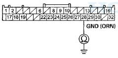
Wire side of female terminals
Is there continuity? YES
-Go to step 15.
NO
-Repair open in the wire between the gauge control module (GND line) and the fuel gauge sending unit, then go to step 27.
15. Connect fuel tank unit 4P connector terminal No. 1 to body ground with a jumper wire.
FUfcL TANK UNIT 4P CONNECTOR
Wire side of female terminals
16. Check for continuity between gauge control module 32P connector terminal No. 27 and body ground.
GAUGE CONTROL MODULE 32P CONNECTOR
Wire side of female terminals
Is there continuity? YES
-Replace the gauge control module (see page 22-351), then go to step 27.
NO
-Repair open in the wire between the gauge control module (signal line) and the fuel gauge sending unit, then go to step 27.
17. Turn the ignition switch to LOCK (0).
18. Remove the fuel tank unit (see page 11-320).
19. Test the fuel gauge sending unit (see page 11-328).
Is the fuel gauge sending unit OK? YES
-Go to step 20.
NO
-Replace the fuel gauge sending unit (see page 11 -324), then go to step 26.
20. Connect the fuel tank unit 4P connector
21. Reconnect the gauge control module 32P connector.
22. Turn the ignition switch to ON (II).
23. Clear the DTC with the HDS.
24. Set the float (A) to the F position.
25. Check the fuel gauge.
Does the gauge move to the full position? YES
-Go to step 33.
NO
-Replace the gauge control module (see page 22-351), then go to step 26.
26. Turn the ignition switch to LOCK (0).
27. Reconnect all connectors.
28. Reinstall all removed parts in the reverse order of removal.
29. Turn the ignition switch to ON (II).
30. Reset the ECM/PCM with the HDS.
31. Do the ECM/PCM idle learn procedure (see page 11-293).
32. Check for Pending or Confirmed DTCs with the HDS.
Is DTC P0463 indicated? YES
-Check for poor connections or loose terminals at the gauge control module and the fuel gauge sending unit, then go to step 1.
NO-
Troubleshooting is complete. If any other Temporary DTCs or DTCs are indicated, go to the indicated DTCs troubleshooting.
33. Turn the ignition switch to LOCK (0).
34. Reinstall all removed parts in the reverse order of removal.
35. Reconnect all connectors.
36. Update the ECM/PCM if it does not have the latest software (see page 11-203), or substitute a known-good ECM/PCM (see page 11-7).
37. Check for Pending or Confirmed DTCs with the HDS.
Is DTC P0463 indicated? YES-
Check for poor connections or loose terminals at the gauge control module and the fuel gauge sending unit. If the ECM/PCM was updated, substitute a known-good ECM/PCM (see page 11-7), then recheck.
If the ECM/PCM was substituted, go to step 1.
NO
-lf the ECM/PCM was updated, troubleshooting is complete. If the ECM/PCM was substituted, replace the original ECM/PCM (see page 11-204). If any other Pending or Confirmed DTCs are indicated, go to the indicated DTCs troubleshooting.

 Fuel Pump Circuit Troubleshooting
If you suspect a problem with the fuel pump, check that
the fuel pump actually runs; when it is on, you will hear
some noise if you listen to the fuel fill port with the fuel
fill cap removed. The ...
See also:
Replacing the High-mount Brake Light Bulb
1. Open the trunk, and remove the
socket from the light assembly by
turning it one-quarter turn counterclockwise.
2. Pull the bulb straight out of its
socket. Push the new bulb straight
int ...
Transmission End Cover
End Cover Installation
Exploded View
Special Tools Required
Mainshaft Holder 07GAB-PF50101
NOTE: Refer to the Exploded View as needed during the
following procedure.
1. Install the mainshaft ...
Front Passenger's Weight Sensor Output Check After
a Vehicle Collision
1. Position the front passenger's seat to the rear most
position, and adjust the seat-back to the forward most
position. Do not move the seat from this position.
2. Drive the vehicle, accelerate ...