 Honda Accord: DTC Troubleshooting
DTC P0122:
TP Sensor A Circuit Low Voltage
NOTE: Before you troubleshoot, record all freeze data and any on-board snapshot, and review the general troubleshooting information (see page 11-3).
1. Turn the ignition switch to ON (II).
2. Clear the DTC with the HDS.
3. Check TP SENSOR A in the DATA LIST with the HDS.
Is there about 0.3 V or less? YES
-Go to step 4.
NO
-lntermittent failure, the system is OK at this time.
Check for poor connections or loose terminals at the throttle body and the ECM/PCM.
4. Check for Pending or Confirmed DTCs with the HDS.
Are DTC P0122 and P0222 indicated at the same time? YES
-Go to step 10.
NO-
Go to step 5.
5. Turn the ignition switch to LOCK (0).
6. Disconnect the throttle body 6P connector.
7. Jump the SCS line with the HDS.
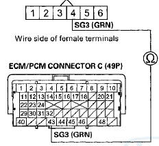
8. Disconnect ECM/PCM connector C (49P).
9. Check for continuity between throttle body 6P connector terminal No. 1 and body ground.
THROTTLE BODY 6P CONNECTOR
Wire side of female terminals
Is there continuity? YES
-Repair short in the wire between the throttle body and the ECM/PCM (C20), then go to step 18.
NO
-Go to step 23.
10. Measure the voltage between throttle body 6P connector terminal No. 2 and body ground.
THROTTLE BODY 6P CONNECTOR
Wire side of female terminals
Is there about 5 V? YES
-Go to step 16.
NO
-Gotostep11.
11. Turn the ignition switch to LOCK (0).
12. Jump the SCS line with the HDS.
13. Disconnect ECM/PCM connector C (49P).
14. Disconnect the throttle body 6P connector.
15. Check for continuity between ECM/PCM connector terminal C12 and throttle body 6P connector terminal No. 2.
THROTTLE BODY 6P CONNECTOR

Terminal side of female terminals
Is there continuity? YES
-Go to step 23.
NO
-Repair open in the wire between the throttle body and the ECM/PCM (C12), then go to step 18.
16. Turn the ignition switch to LOCK (0).
17. Replace the throttle body (see page 11-335).
18. Reconnect all connectors.
19. Turn the ignition switch to ON (II).
20. Reset the ECM/PCM with the HDS.
21. Do the ECM/PCM idle learn procedure (see page 11-293).
22. Check for Pending or Confirmed DTCs with the HDS.
Is DTC P0122 indicated?
YES
-Check for poor connections or loose terminals at the throttle body and the ECM/PCM, then go to step 1.
NO
-Troubleshooting is complete. If any other Pending or Confirmed DTCs are indicated, go to the indicated DTCs troubleshooting.
23. Reconnect all connectors.
24. Update the ECM/PCM if it does not have the latest software (see page 11-203), or substitute a known-good ECM/PCM (see page 11-7).
25. Check for Pending or Confirmed DTCs with the HDS.
Is DTC P0122 Indicated? YES
-Check for poor connections or loose terminals at the throttle body and the ECM/PCM. If the ECM/PCM was updated, substitute a known-good ECM/PCM (see page 11-7), then recheck. If the ECM/PCM was substituted, go to step 1.
NO
-lf the ECM/PCM was updated, troubleshooting is complete. If the ECM/PCM was substituted, replace the original ECM/PCM (see page 11-204). If any other Pending or Confirmed DTCs are indicated, go to the indicated DTCs troubleshooting.
DTC P0123:
TP Sensor A Circuit High Voltage
NOTE: Before you troubleshoot, record all freeze data and any on-board snapshot, and review the general troubleshooting information (see page 11-3).
1. Turn the ignition switch to ON (II).
2. Clear the DTC with the HDS.
3. Check TP SENSOR A in the DATA LIST with the HDS.
Is there about 4.8 Vor more? YES-
Go to step 4.
NO
-lntermittent failure, the system is OK at this time.
Check for poor connections or loose terminals at the throttle body and the ECM/PCM.
4. Check for Pending or Confirmed DTCs with the HDS.
Are DTC P0123 and P0223 indicated at the same time? YES
-Go to step 13.
NO
-Go to step 5.
5. Turn the ignition switch to LOCK (0).
6. Disconnect the throttle body BP connector.
7. Turn the ignition switch to ON (II).
8. Measure the voltage between throttle body 6P connector terminal No. 1 and body ground.
1HROTTLE BODY 6P CONNECTOR
Wire side of female terminals
Is there about 5 V? YES
-Go to step 18.
NO
-Go to step 9.
9. Turn the ignition switch to LOCK (0).
10. Jump the SCS line with the HDS.
11. Disconnect ECM/PCM connector C (49P).
12. Check for continuity between ECM/PCM connector terminal C20 and throttle body 6P connector terminal No. 1.
THROTTLE BODY 6P CONNECTOR
Terminal side of female terminals
Is there continuity? YES-
Go to step 25.
NO
-Repair open in the wire between the throttle body and the ECM/PCM (C20), then go to step 20.
13. Turn the ignition switch to LOCK (0).
14. Disconnect the throttle body 6P connector.
15. Jump the SCS line with the HDS.
16. Disconnect ECM/PCM connector C (49P).
17. Check for continuity between ECM/PCM connector terminal C43 and throttle body 6P connector terminal No. 4.
THROTTLE BODY 6P CONNECTOR

Terminal side of female terminals
Is there continuity? YES
-Go to step 25.
NO
-Repair open in the wire between the throttle body and the ECM/PCM (C43), then go to step 20.
18. Turn the ignition switch to LOCK (0).
19. Replace the throttle body (see page 11-335).
20. Reconnect all connectors.
21. Turn the ignition switch to ON (II).
22. Reset the ECM/PCM with the HDS.
23. Do the ECM/PCM idle learn procedure (see page 11-293).
24. Check for Pending or Confirmed DTCs with the HDS.
Is DTC P0123 indicated? YES
-Check for poor connections or loose terminals at the throttle body and the ECM/PCM, then go to step 1.
NO
-Troubleshooting is complete. If any other Pending or Confirmed DTCs are indicated, go to the indicated DTCs troubleshooting.
25. Reconnect all connectors.
26. Update the ECM/PCM if it does not have the latest software (see page 11 -203), or substitute a known-good ECM/PCM (see page 11-7).
27. Check for Pending or Confirmed DTCs with the HDS.
Is DTC P0123 indicated? YES
-Check for poor connections or loose terminals at the throttle body and the ECM/PCM. If the ECM/PCM was updated, substitute a known-good ECM/PCM (see page 11 -7), then recheck. If the ECM/PCM was substituted, go to step 1.
NO
-lf the ECM/PCM was updated, troubleshooting is complete. If the ECM/PCM was substituted, replace the original ECM/PCM (see page 11-204). If any other Pending or Confirmed DTCs are indicated, go to the indicated DTCs troubleshooting.
DTC P0222
: TP Sensor B Circuit Low Voltage
NOTE: Before you troubleshoot, record all freeze data and any on-board snapshot, and review the general troubleshooting information (see page 11-3).
1. Turn the ignition switch to ON (II).
2. Clear the DTC with the HDS.
3. Check TP SENSOR B in the DATA LIST with the HDS.
Is there about 0.3 V or less? YES-
Go to step 4.
NO
-lntermittent failure, the system is OK at this time.
Check for poor connections or loose terminals at the throttle body and the ECM/PCM.
Are DTC P0122 and P0222 indicated at the same time? YES
-Go to step 10.
NO
-Go to step 5.
5. Turn the ignition switch to LOCK (0).
6. Disconnect the throttle body 6P connector.
7. Jump the SCS line with the HDS.
8. Disconnect ECM/PCM connector C (49P).
9. Check for continuity between throttle body 6P connector terminal No. 3 and body ground.
THROTTLE BODY 6P CONNECTOR
Wire side of female terminals
Is there continuity? YES-
Repair short in the wire between the throttle body and the ECM/PCM (C21), then go to step 18.
NO-
Go to step 23.
10. Measure the voltage between throttle body 6P connector terminal No. 2 and body ground.
1HROTTLE BODY 6P CONNECTOR

Wire side of female terminals
Is there about 5 V? YES
-Go to step 16.
NO
-Go to step 11.
11. Turn the ignition switch to LOCK (0).
12. Jump the SCS line with the HDS.
13. Disconnect ECM/PCM connector C (49P).
14. Disconnect the throttle body 6P connector.
15. Check for continuity between ECM/PCM connector terminal C12 and throttle body 6P connector terminal No. 2.
THROTTLE BODY i P CONNECTOR
Terminal side of female terminals
Is there continuity? YES
-Go to step 23.
NO
-Repair open in the wire between the throttle body and the ECM/PCM (C12), then go to step 18.
16. Turn the ignition switch to LOCK (0).
17. Replace the throttle body (see page 11 -335).
18. Reconnect all connectors.
19. Turn the ignition switch to ON (II).
20. Reset the ECM/PCM with the HDS.
21. Do the ECM/PCM idle learn procedure (see page 11-293).
22. Check for Pending or Confirmed DTCs with the HDS.
Is DTC P0222 indicated? YES
-Check for poor connections or loose terminals at the throttle body and the ECM/PCM, then go to step 1.
NO-
Troubleshooting is complete. If any other Pending or Confirmed DTCs are indicated, go to the indicated DTCs troubleshooting.
23. Reconnect all connectors.
24. Update the ECM/PCM if it does not have the latest software (see page 11-203), or substitute a known-good ECM/PCM (see page 11-7).
25. Check for Pending or Confirmed DTCs with the HDS.
Is DTC P0222 indicated? YES
-Check for poor connections or loose terminals at the throttle body and the ECM/PCM. If the ECM/PCM was updated, substitute a known-good ECM/PCM (see page 11-7), then recheck. If the ECM/PCM was substituted, go to step 1.
NO-
lf the ECM/PCM was updated, troubleshooting is complete. If the ECM/PCM was substituted, replace the original ECM/PCM (see page 11-204). If any other Pending or Confirmed DTCs are indicated, go to the indicated DTCs troubleshooting.
DTC P0223:
TP Sensor B Circuit High Voltage
NOTE: Before you troubleshoot, record all freeze data and any on-board snapshot, and review the general troubleshooting information (see page 11-3).
1. Turn the ignition switch to ON (II).
2. Clear the DTC with the HDS.
3. Check TP SENSOR B in the DATA LIST with the HDS.
Is there about 4.8 V or more? YES-
Go to step 4.
NO
-lntermittent failure, the system is OK at this time.
Check for poor connections or loose terminals at the throttle body and the ECM/PCM.B 4. Check for Pending or Confirmed DTCs with the HDS.
Are DTC P0123 and P0223 Indicated at the same time? YES
-Go to step 13.
NO
-Go to step 5.
5. Turn the ignition switch to LOCK (0).
6. Disconnect the throttle body 6P connector.
7. Turn the ignition switch to ON (II).
8. Measure the voltage between throttle body 6P connector terminal No. 3 and body ground.
THROTTLE BODY 6P CONNECTOR

Wire side of female terminals
Is there about 5 V? YES
-Go to step 18.
NO-
Go to step 9.
9. Turn the ignition switch to LOCK (0).
10. Jump the SCS line with the HDS.
11. Disconnect ECM/PCM connector C (49P).
12. Check for continuity between ECM/PCM connector terminal C21 and throttle body 6P connector terminal No. 3.
THROTTLE BODY 6P CONNECTOR

Terminal side of female terminals
Is there continuity? YES
-Go to step 25.
NO-Repair open in the wire between the throttle body and the ECM/PCM (C21), then go to step 20.
13. Turn the ignition switch to LOCK (0).
14. Disconnect the throttle body 6P connector.
15. Jump the SCS line with the HDS.
16. Disconnect ECM/PCM connector C (49P).
17. Check for continuity between ECM/PCM connector terminal C43 and throttle body 6P connector terminal No. 4.
THROTTLE BODY 6P CONNECTOR
Terminal side of female terminals
Is there continuity? YES
-Go to step 25.
NO
-Repair open in the wire between the throttle body and the ECM/PCM (C43), then go to step 20.
18. Turn the ignition switch to LOCK (0).
19. Replace the throttle body (see page 11-335).
20. Reconnect all connectors.
21. Turn the ignition switch to ON (II).
22. Reset the ECM/PCM with the HDS.
23. Do the ECM/PCM idle learn procedure (see page 11-293).
24. Check for Pending or Confirmed DTCs with the HDS.
Is DTC P0223 indicated? YES-
Check for poor connections or loose terminals at the throttle body and the ECM/PCM, then go to step 1.
NO
-Troubleshooting is complete. If any other Pending or Confirmed DTCs are indicated, go to the indicated DTCs troubleshooting
25. Reconnect all connectors.
26. Update the ECM/PCM if it does not have the latest software (see page 11-203), or substitute a known-good ECM/PCM (see page 11-7).
27. Check for Pending or Confirmed DTCs with the HDS.
Is DTC P0223 indicated? YES-
Check for poor connections or loose terminals at the throttle body and the ECM/PCM. If the ECM/PCM was updated, substitute a known-good ECM/PCM (see page 11 -7), then recheck. If the ECM/PCM was substituted, go to step 1.
NO-
lf the ECM/PCM was updated, troubleshooting is complete. If the ECM/PCM was substituted, replace the original ECM/PCM (see page 11-204). If any other Pending or Confirmed DTCs are indicated, go to the indicated DTCs troubleshooting.
DTC P1658:
ETCS Control Relay ON Malfunction
NOTE: Before you troubleshoot, record all freeze data and any on-board snapshot, and review the general troubleshooting information (see page 11-3).
1. Turn the ignition switch to ON (II).
2. Do the ETCS TEST in the INSPECTION MENU with the HDS.
Is the RELA Y circuit OK? YES
-lntermittent failure, the system is OK at this time.
Check for poor connections or loose terminals at the ETCS control relay and the ECM/PCM.
NO-
Go to step 3.
3. Turn the ignition switch to LOCK (0).
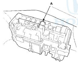
4. Remove the ETCS control relay (A) from the under-hood fuse/relay box.
5. Test the ETCS control relay (see page 22-93).
Is the ETCS control relay OK? YES-Go to step 6.
NO-Replace the ETCS control relay, then go to step 13.
6. Jump the SCS line with the HDS.
7. Disconnect ECM/PCM connector A (49P).
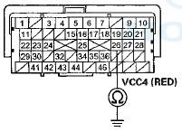
8. Check for continuity between ECM/PCM connector terminal A21 and body ground.
ECM/PCM CONNECTOR A (49P)
Terminal side of female terminals
Is there continuity? YES-Repair short in the wire between the ECM/PCM (A21) and the ETCS control relay, then go to step 13.
NO-Go to step 9.
9. Disconnect ECM/PCM connector C (49P).
10. Turn the ignition switch to ON (II).
11. Measure the voltage between ECM/PCM connector terminal C1 and body ground.
ECM/PCM CONNECTOR C (49P)

Terminal side of female terminals
Is there battery voltage? YES
-Repair short to power in the wire between the ECM/PCM (C1) and the ETCS control relay, then go to step 12.
NO
-Go to step 18.
12. Turn the ignition switch to LOCK (0).
13. Reconnect all connectors.
14. Turn the ignition switch to ON (II).
15. Reset the ECM/PCM with the HDS.
18. Do the ECM/PCM idle, learn procedure (see page 11-293).
17. Check for Pending or Confirmed DTCs with the HDS.
Is DTC P1658 indicated?: , YES
-Check for poor connections or loose terminals at the ETCS control relay and the ECM/PCM, then go to step 1.
NO
-Troubleshooting is complete. If any other Pending or Confirmed-DTCs are indicated, go to the indicated DTCs troubleshooting.
18. Turn the ignition switch to LOCK (0).
19. Reconnect all connectors.
20. Update the. ECM/PCM if it does not have the latest software (see page 11 -203), or substitute a known-good ECM/PCM (see page 11 -7).
21. Check for Pending or Confirmed DTCs with the HDS.
Is DTC P1658 indicated? YES
-Check for poor connections or loose terminals at the ETCS control relay and the ECM/PCM. If the ECM/PCM was updated, substitute a known-good ECM/PCM (see page 11 -7), then recheck. If the ECM/PCM was substituted, go to step 1.
NO
-lf the ECM/PCM was updated, troubleshooting is complete. If the ECM/PCM was substituted, replace the original ECM/PCM (see page 11-204). If any other Pending or Confirmed DTCs are indicated, go to the indicated DTCs troubleshooting.
DTC P18SS
: ETCS Control Relay OFF Malfunction
NOTE: Before you troubleshoot, record all freeze data and any on-board snapshot, and review the general troubleshooting information (see page 11-3).
1. Turn the ignition switch to ON (II).
2. Clear the DTC with the HDS.
3. Check for Pending or Confirmed DTCs with the HDS.
Is DTC P1659 indicated? YES
-Go to step 4.
NO
-lntermittent failure, the system is OK at this time.
Check for poor connections or loose terminals at the ETCS control relay and the ECM/PCM.
4. Turn the ignition switch to LOCK (0).
5. Check the No. 18 DBW (ETCS) (15 A) fuse in the under-hood fuse/relay box.
Is the fuse OK? YES
-Go to step 6..
NO
-Go to step 17.
6. Remove the ETCS control relay (A) from the under-hood fuse/relay box.

7. Test the ETCS control relay (see page 22-93).
Is the ETCS control relay OK? YES
-Go to step 8.
NO-
Replace the ETCS control relay, then go to step 23.
8. Turn the ignition switch to ON (II).
9. Measure the voltage between ETCS control relay 4P connector terminal No. 4 and body ground.
ETCS CONTROL RELAY 4P CONNECTOR

Terminal side of female terminals
Is there battery voltage? YES
-Go to step 10.
NO
-Replace the under-hood fuse/relay box (see page 22-85), then go to step 22.
10. Measure the voltage between ETCS control relay 4P connector terminal No. 1 and body ground.
ETCS CONTROL RELAY 4P CONNECTOR

Terminal side of female terminals
Is there battery voltage? YES
-Go to step 11.
NO
-Replace the under-hood fuse/relay box (see page 22-85), then go to step 22.
11. Turn the ignition switch to LOCK (0).
12. Jump the SCS line with the HDS.
13. Disconnect ECM/PCM connector C (49P).
14. Check for continuity between ETCS control relay 4P connector terminal No. 2 and ECM/PCM connector terminal C1.
ETCS CONTROL RELAY 4P CONNECTOR

Terminal side of female terminals
Is there continuity? YES
-Go to step 15.
NO
-Repair open in the wire between the ECM/PCM (C1) and the ETCS control relay, then go to step 23.
15. Disconnect ECM/PCM connector A (49P).
18. Check for continuity between ETCS control relay 4P connector terminal No. 3 and ECM/PCM connector terminal A21.
ETCS CONTROL RELAY 4P CONNECTOR

Terminal side of female terminals
Is there continuity? YES
-Go to step 28.
NO
-Repair open in the wire between the ECM/PCM (A21) and the ETCS control relay, then go to step 23.
17. Remove the ETCS control relay (A) from the under-hood fuse/relay box.
18. Jump the SCS line with the HDS.
19. Disconnect ECM/PCM connector C (49P).
20. Check for continuity between ECM/PCM connector terminal C1 and body ground.
ECM/PCM CONNECTOR C (49P)

Terminal side of female terminals
Is there continuity? YES
-Repair short in the wire between the ECM/PCM (C1) and the ETCS control relay, then go to step 23.
NO-
Go to step 21.
21. Check for continuity between ETCS control relay 4P connector terminal No. 1 and body ground.
ETCS CONTROL RELAY 4P CONNECTOR

Terminal side of female terminals
Is there continuity? YES
-Replace the under-hood fuse/relay box (see page 22-85), then go to step 23.
NO
-Go to step 28.
22. Turn the Ignition switch to LOCK (0).
23. Reconnect all connectors.
24. Turn the Ignition switch to ON (II).
25. Reset the ECM/PCM with the HDS.
26. Do the ECM/PCM Idle learn procedure (see page 11-293).
27. Check for Pending or Confirmed DTCs with the HDS.
Is DTC P1659 indicated? YES-
Check for poor connections or loose terminals at the ETCS control relay and the ECM/PCM, then go to step 1.
NO
-Troubleshooting is complete. If any other Pending or Confirmed DTCs are indicated, go to the indicated DTCs troubleshooting.
28. Reconnect all connectors.
29. Update the ECM/PCM If It does not have the latest software (see page 11-203), or substitute a known-good ECM/PCM (see page 11 -7).
30. Check for Pending or Confirmed DTCs with the HDS.
Is DTC P1659 indicated? YES
-Check for poor connections or loose terminals at the ETCS control relay and the ECM/PCM. If the ECM/PCM was updated, substitute a known-good ECM/PCM (see page 11-7), then recheck. If the ECM/PCM was substituted, go to step 1.
NO-l
f the ECM/PCM was updated, troubleshooting Is complete. If the ECM/PCM was substituted, replace the original ECM/PCM (see page 11-204). If any other Pending or Confirmed DTCs are Indicated, go to the Indicated DTCs troubleshooting.
DTC P1683:
Throttle Valve Default Position Spring Performance Problem
Do not insert your fingers into the installed throttle body when you turn the ignition switch to ON (II) or while the ignition switch is in ON (II). If you do, you will seriously injure your fingers if the throttle valve is activated.
NOTE: Before you troubleshoot, record all freeze data and any on-board snapshot, and review the general troubleshooting information (see page 11-3).
1. Turn the ignition switch to ON (II).
2. Clear the DTC with the HDS.
3. Start the engine. Hold the engine speed at 3,000 rpm without load (A/T in P or N, M/T in neutral) until the radiator fan comes on, then let it idle.
4. Turn the ignition switch to LOCK (0), and wait 10 seconds.
5. Turn the ignition switch to ON (II).
6. Check for Pending or Confirmed DTCs with the HDS.
Is DTC P1683 indicated? YES
-Go to step 7.
NO
-lntermittent failure, the system is OK at this time.
Check for poor connections or loose terminals at the throttle body and the ECM/PCM.
7. Turn the ignition switch to LOCK (0).
8. Disconnect the intake air duct from the throttle body (see page 11-335).
9. Push the throttle valve closed as shown.

10. Release the throttle valve.
Does the throttle valve return? YES
-Clean the throttle body (see page 11 -332), then go to step 12 and recheck. If DTC P1683 is indicated, go to step 11.
NO
-Go to step 11.
11. Replace the throttle body (see page 11-335).
12. Turn the ignition switch to ON (II).
13. Reset the ECM/PCM with the HDS.
14. Do the ECM/PCM idle learn procedure (see page 11-293).
15. Turn the ignition switch to LOCK (0), and wait 10 seconds.
16. Turn the ignition switch to ON (II).
17. Check for Pending or Confirmed DTCs with the HDS.
Is DTC P1683 indicated? YES-
Check for poor connections or loose terminals at the throttle body and the ECM/PCM, then go to step 1.
NO-
Troubleshooting is complete. If any other Pending or Confirmed DTCs are indicated, go to the indicated DTCs troubleshooting.
DTC P1684:
Throttle Valve Return Spring Performance Problem
Do not insert your fingers into the installed throttle body when you turn the ignition switch to ON (II) or while the ignition switch is in ON (II). If you do, you will seriously injure your fingers if the throttle valve is activated.
NOTE: Before you troubleshoot, record all freeze data and any on-board snapshot, and review the general troubleshooting information (see page 11-3).
1. Turn the ignition switch to ON (II).
2. Clear the DTC with the HDS.
3. Start the engine. Hold the engine speed at 3,000 rpm without load (A/T in P or N, M/T in neutral) until the radiator fan comes on, then let it idle.
4. Turn the ignition switch to LOCK (0), and wait 10 seconds.
5. Turn the ignition switch to ON (II).
6. Check for Pending or Confirmed DTCs with the HDS.
Is DTC P1684 indicated? YES-
Go to step 7.
NO
-lntermittent failure, the system is OK at this time.
Check for poor connections or loose terminals at the throttle body and the ECM/PCM.
7. Turn the ignition switch to LOCK (0).
8. Disconnect the intake air duct from the throttle body (see page 11-335).
9. Push the throttle valve open as shown.

10. Release the throttle valve.
Does the throttle valve return? YES
-Clean the throttle body (see page 11-332), then go to step 12 and recheck. If DTC P1684 is indicated, go to step 11.
NO
-Go to step 11.
11. Replace the throttle body (see page 11 -335).
12. Turn the ignition switch to ON (II).
13. Reset the ECM/PCM with the HDS.
14. Do the ECM/PCM idle learn procedure (see page 11-293).
15. Turn the ignition switch to LOCK (0), and wait 10 seconds.
16. Turn the ignition switch to ON (II).
17. Check for Pending or Confirmed DTCs with the HDS.
Is DTC P1684 indicated? YES-
Check for poor connections or loose terminals at the throttle body and the ECM/PCM, then go to step 1.
NO
-Troubleshooting is complete. If any other Pending or Confirmed DTCs are indicated, go to the indicated DTCs troubleshooting.
DTC P2101:
Electronic Throttle Control System (ETCS) Malfunction
Do not insert your fingers into the installed throttle body when you turn the ignition switch to ON (II) or while the ignition switch is in ON (II). If you do, you will seriously injure your fingers if the throttle valve is activated.
NOTE: Before you troubleshoot, record all freeze data and any on-board snapshot, and review the general troubleshooting information (see page 11-3).
1. Turn the ignition switch to ON (II).
2. Clear the DTC with the HDS.
3. Do the ETCS TEST in the INSPECTION MENU with the HDS.
4. Check for Pending or Confirmed DTCs with the HDS.
Is DTC P2101 indicated? YES-Go to step 7.
NO-Go to step 5.
5. Test-drive the vehicle for several minutes in the range of these recorded freeze data parameters:
- ENGINE SPEED
- VSS
- APPSENSOR
6. Check for Pending or Confirmed DTCs with the HDS.
Is DTC P2101 indicated? YES
-Go to step 7.
NO-
lntermittent failure, the system is OK at this time.
Check for poor connections or loose terminals at the throttle body and the ECM/PCM, then clean the throttle body (see page 11-332).
7. Turn the ignition switch to LOCK (0).
8. Disconnect the intake air duct from the throttle body (see page 11-335).
9. Turn the ignition switch to ON (II).
10. Clear the DTC with the HDS.
11. Do the ETCS TEST in the INSPECTION MENU with the HDS.
12. Visually check the throttle valve operation.
Does the throttle valve operate smoothly? YES-Clean the throttle body (see page 11-335), then go to step 22 and recheck. If DTC P2101 is indicated, go to step 19.
NO-Go to step 13. .
13. Turn the ignition switch to LOCK (0).
14. Disconnect the throttle body 6P connector.
15. Jump the SCS line with the HDS.
16. Disconnect ECM/PCM connector C (49P).
17. Connect throttle body 6P connector terminals No. 5 and No. 6 with a jumper wire.
THROTTLE BODY 6P CONNECTOR
Wire side of female terminals
18. Check for continuity between ECM/PCM connector terminals C3 and C4.
ECM/PCM CONNECTOR C (49P)

Terminal side of female terminals
Is there continuity? YES
-Go to step 27.
NO
-Repair open in the wires between the throttle body and the ECM/PCM (C3, C4), then go to step 21.
19. Turn the ignition switch to LOCK (0).
20. Replace the throttle body (see page 11-335).
21. Reconnect all connectors.
22. Turn the ignition switch to ON (II).
23. Reset the ECM/PCM with the HDS.
24. Do the ECM/PCM idle learn procedure (see page 11-293).
25. Test-drive the vehicle for several minutes in the range of these recorded freeze data parameters:
- ENGINE SPEED
- VSS
- APPSENSOR
26. Check for Pending or Confirmed DTCs with the HDS.
Is DTC P2101 indicated? YES
-Check for poor connections or loose terminals at the throttle body and the ECM/PCM, then clean the throttle body (see page 11-332), and go to step 1.
NO
-Troubleshooting is complete. If any other Pending or Confirmed DTCs are indicated, go to the indicated DTCs troubleshooting.
27. Reconnect all connectors.
28. Update the ECM/PCM if it does not have the latest software (see page 11-203), or substitute a known-good ECM/PCM (see page 11-7).
29. Test-drive the vehicle for several minutes in the range of these recorded freeze data parameters:
- ENGINE SPEED
- VSS
- APP SENSOR
30. Check for Pending or Confirmed DTCs with the HDS.
Is DTC P2101 indicated? YES-Check for poor connections or loose terminals at the throttle body and the ECM/PCM. If the ECM/PCM was updated, substitute s known-good ECM/PCM (see page 11 -7), then go to step 29. If the ECM/PCM was substituted, go to step 1.
NO-lf the ECM/PCM was updated, troubleshooting is complete. If the ECM/PCM was substituted, replace the original ECM/PCM (see page 11-204). If any other Pending or Confirmed DTCs are indicated, go to the indicated DTCs troubleshooting
DTC P2118:
Throttle Actuator Current Range/Performance Problem
NOTE: Before you troubleshoot, record all freeze data and any on-board snapshot, and review the general troubleshooting information (see page 11-3).
1. Turn the ignition switch to ON (II).
2. Clear the DTC with the HDS.
3. Slowly press the accelerator pedal to the floor.
4. Check for Pending or Confirmed DTCs with the HDS.
Is DTC P2118 indicated? YES
-Go to step 5.
NO
-intermittent failure, the system is OK at this time.
Check for poor connections or loose terminals at the throttle body and the ECM/PCM.
5. Turn the ignition switch to LOCK (0).
6. Jump the SCS line with the HDS.
7. Disconnect the throttle body 6P connector.
8. Disconnect PCM connector C (49P).
9. Check for continuity between ECM/PCM connector terminal C43 and throttle body BP connector terminal No. 4.
THROTTLE BODY 6P CONNECTOR

Is there continuity? YES
-Go to step 10.
NO
-Repair open in the wire between the throttle body and the ECM/PCM (043), then go to step 14.
10. Check for continuity between throttle body 6P connector terminals No. 5 and No. 6.
THKOTTLE BODY 6P CONNECTOR
Wire side of female terminals Is there continuity? YES
-Repair short in the wires between throttle body 6P connector terminal No. 5 (ETCS-” line) and No. 6 (ETCS+ line), then go to step 14.
NO
-Go to step 11.
11. Check for continuity between body ground and throttle body 6P connector terminals No. 5 and No. 6 individually.
THROTTLE BODY 6P CONNECTOR

Wire side of female terminals
Is there continuity? YES-Repair short in the wire between throttle body 6P connector and body ground, then go to step 14.
NO-Go to step 12.
12. At the throttle body side, measure the resistance between throttle body 6P connector terminals No. 5 and No. 6 with the throttle fully closed.
THROTTLE BODY 6P CONNECTOR
Terminal side of male terminals
Is there about 1.0 Dor less? YES
-Go to step 13.
NO
-Go to step 22.
13. Replace the throttle body (see page 11-335).
14. Reconnect all connectors.
15. Turn the ignition switch to ON (II).
16. Reset the ECM/PCM with the HDS.
17. Do the ECM/PCM idle learn procedure (see page 11-293).
18. Turn the ignition switch to LOCK (0).
19. Turn the ignition switch to ON (II).
20. Slowly press the accelerator pedal to the floor.
21. Check for Pending or Confirmed DTCs with the HDS.
Is DTC P2118 indicated? YES-
Check for poor connections or loose terminals at the throttle body and the ECM/PCM, then go to step 1.
NO
-Troubleshooting is complete. If any other Pending or Confirmed DTCs are indicated, go to the indicated DTCs troubleshooting.
22. Reconnect all connectors.
23. Update the ECM/PCM if it does not have the latest software (see page 11-203), or substitute a known-good ECM/PCM (see page 11 -7).
24. Turn the ignition switch to LOCK (0).
25. Turn the ignition switch to ON (II).
26. Slowly press the accelerator pedal to the floor.
27. Check for Pending or Confirmed DTCs with the HDS.
Is DTC P2118 indicated? YES-
Check for poor connections or loose terminals at the throttle body and the ECM/PCM. If the ECM/PCM was updated, substitute a known-good ECM/PCM (see page 11 -7), then go to step 26. If the ECM/PCM was substituted, go to step 1.
NO
-lf the ECM/PCM was updated, troubleshooting is complete. If the ECM/PCM was substituted, replace the original ECM/PCM (see page 11-204). If any other Pending or Confirmed DTCs are indicated, go to the indicated DTCs troubleshooting
DTC P2122
:APP Sensor A (TP Sensor D) 1 Circuit Low Voltage
NOTE: Before you troubleshoot, record all freeze data and any on-board snapshot, and review the general troubleshooting information (see page 11-3).
1. Turn the ignition switch to ON (II).
2. Check APP SENSOR A in the DATA LIST with the HDS.
Is there about 0.2 V or less? YES
-Go to step 3.
NO
-lntermittent failure, the system is OK at this time.
Check for poor connections or loose terminals at the APP sensor and the ECM/PCM
3. Turn the ignition switch to LOCK (0).
4. Disconnect the APP sensor 6P connector.
5. Turn the ignition switch to ON (II).
6. Measure the voltage between APP sensor 6P connector terminals No. 2 and No. 3.
APP SENSOR 6P CONNECTOR
Wire side of female terminals
Is there about 5 V? YES
-Go to step 7.
NO
-Go to step 17.
7 Turn the ignition switch to LOCK (0).
8. Jump the SCS line with the HDS.
9. Disconnect ECM/PCM connector A (49P).
10. Check for continuity between APP sensor 6P connector terminal No. 1 and body ground.
APP SENSOR 6P CONNECTOR
Wire side of female terminals
Is there continuity? YES
-Repair short in the wire between the ECM/PCM (A18) and the APP sensor, then go to step 24.
NO
-Go to step 11.
11. Connect APP sensor 6P connector terminal No. 1 to body ground with a jumper wire.
APP SENSOR 6P CONNECTOR
Wire side of female terminals
12. Check for continuity between ECM/PCM connector terminal A18 and body ground.
ECM/PCM CONNECTOR A (49P)

Terminal side of female terminals
Is there continuity? YES
-Go to step 13.
NO
-Repair open in the wire between the ECM/PCM (A18) and the APP sensor, then go to step 24.
13. Reconnect ECM/PCM connector A (49P).
14. Connect APP sensor 6P connector terminals No. 1 and No. 3 with a jumper wire.
APP SENSOR 6P CONNECTOR

Wire side of female terminals
15. Turn the ignition switch to ON (II).
16. Check APP SENSOR A in the DATA LIST with the HDS.
Is there about 0.2 Vor less? YES
-Go to step 29.
NO
-Go to step 22.
17. Turn the ignition switch to LOCK (0).
18. Jump the SCS line with the HDS.
19. Disconnect ECM/PCM connector A (49P).
20. Connect APP sensor 6P connector terminal No. 3 to body ground with a jumper wire.
APP SENSOR 6P CONNECTOR
Wire side of female terminals
21. Check for continuity between ECM/PCM connector terminal A26 and body ground.
ECM/PCM CONNECTOR A (49P)
Terminal side of female terminals
Is there continuity? YES
-Go to step 30.
NO
-Repair open in the wire between the ECM/PCM (A26) and the APP sensor, then go to step 24.
22. Turn the ignition switch to LOCK (0).
23. Replace the accelerator pedal module (see page 11-240).
24. Reconnect all connectors.
25. Turn the ignition switch to ON (II).
26. Reset the ECM/PCM with the HDS.
27. Do the ECM/PCM idle learn procedure (see page 11-293).
28. Check for Pending or Confirmed DTCs with the HDS.
Is DTC P2122 indicated? YES-
Check for poor connections or loose terminals at the APP sensor and the ECM/PCM, then go to step 1.
NO
-Troubleshooting Is complete. If any other Pending or Confirmed DTCs are indicated, go to the indicated DTCs troubleshooting
29. Turn the ignition switch to LOCK (0).
30. Reconnect all connectors.
31. Update the ECM/PCM if it does not have the latest software (see page 11-203), or substitute a known-good ECM/PCM (see page 11-7).
32. Check for Pending or Confirmed DTCs with the HDS.
Is DTC P2122 indicated? YES
-Check for poor connections or loose terminals at the APP sensor and the ECM/PCM. If the ECM/PCM was updated, substitute a known-good ECM/PCM (see page 11-7), then recheck. If the ECM/PCM was substituted, go to step 1.
NO
-lf the ECM/PCM was updated, troubleshooting is complete. If the ECM/PCM was substituted, replace the original ECM/PCM (see page 11-204). If any other Pending or Confirmed DTCs are indicated, go to the indicated DTCs troubleshooting.
DTC P2123:
APP Sensor A (TP Sensor D) Circuit High Voltage
NOTE: Before you troubleshoot record all freeze data and any on-board snapshot, and review the general troubleshooting information (see page 11-3).
1. Turn the ignition switch to ON (II).
2. Check APP SENSOR A in the DATA LIST with the HDS.
Is there about 4.9 Vor more? YES
-Go to step 3.
NO
-lntermittent failure, the system is OK at this time.
Check for poor connections or loose terminals at the APP sensor and the ECM/PCM.B 3. Turn the ignition switch to LOCK (0).
4. Disconnect the APP sensor 6P connector.
5. Turn the ignition switch to ON (II).
6. Measure the voltage between APP sensor 6P connector terminals No. 2 and No. 3.
APP SENSOR 6P CONNECTOR
Wire side of female terminals
Is there about 5 V? YES
-Go to step 12.
NO
-Go to step 7.
7 Turn the ignition switch to LOCK (0).
8. Jump the SCS line with the HDS.
9. Disconnect ECM/PCM connector A (49P).
10. Connect APP sensor 6P connector terminal No. 2 to body ground with a jumper wire.
APP SENSOR 6P CONNECTOR
Wire side of female terminals
11. Check for continuity between ECM/PCM connector terminal A36 and body ground.
ECM/PCM CONNECTOR A (49P)
Terminal side of female terminals
Is there continuity? YES
-Go to step 19.
NO
-Repair open in the wire between the ECM/PCM (A36) and the APP sensor, then go to step 14.
12. Turn the ignition switch to LOCK (0).
13. Replace the accelerator pedal module (see page 11-240).
14. Reconnect all connectors.
15. Turn the ignition switch to ON (II).
16. Reset the ECM/PCM with the HDS.
17. Do the ECM/PCM idle learn procedure (see page 11-293).
18. Check for Pending or Confirmed DTCs with the HDS.
Is DTC P2123 indicated? YES
-Check for poor connections or loose terminals at the APP sensor and the ECM/PCM, then go to step 1.
NO
-Troubieshooting is complete. If any other Pending or Confirmed DTCs are indicated, go to the indicated DTCs troubleshooting.
19. Reconnect all connectors.
20. Update the ECM/PCM if it does not have the latest software (see page 11 -203), or substitute a known-good ECM/PCM (see page 11-7).
21. Check for Pending or Confirmed DTCs with the HDS.
Is DTC P2123 indicated? YES
-Check for poor connections or loose terminals at the APP sensor and the ECM/PCM. If the ECM/PCM was updated, substitute a known-good ECM/PCM (see page 11 -7), then recheck. If the ECM/PCM was substituted, go to step 1.
NO
-lf the ECM/PCM was updated, troubleshooting is complete. If the ECM/PCM was substituted, replace the original ECM/PCM (see page 11-204). If any other Pending or Confirmed DTCs are indicated, go to the indicated DTCs troubleshooting.
DTC P2127:
APP Sensor B (TP Sensor E) Circuit Low Voltage
NOTE: Before you troubleshoot, record all freeze data and any on-board snapshot, and review the general troubleshooting information (see page 11-3).
1. Turn the ignition switch to ON (II).
2. Check APP SENSOR B in the DATA LIST with the HDS.
Is there about 0.2 V or less? YES
-Go to step 3.
NO
-lntermittent failure, the system is OK at this time.
Check for poor connections or loose terminals at the APP sensor and the ECM/PCM.
3. Turn the ignition switch to LOCK (0).
4. Disconnect the APP sensor 6P connector.
5. Turn the ignition switch to ON (II).
6. Measure the voltage between APP sensor 6P connector terminals No. 5 and No. 6.
APP SENSOR 6P CONNECTOR
Wire side of female terminals
Is there about 5 V? YES-
Go to step 7.
NO
-Go to step 17.
7. Turn the ignition switch to LOCK (0).
8. Jump the SCS line with the HDS.
9. Disconnect ECM/PCM connector A (49P).
10. Check for continuity between APP sensor 6P connector terminal No. 4 and body ground.
APP SENSOR 6P CONNECTOR
Wire side of female terminals
Is there continuity? YES
-Repair short in the wire between the ECM/PCM (A19) and the APP sensor, then go to step 24.
NO
-Go to step 11.
11. Connect APP sensor BP connector terminal No. 4 to body ground with a jumper wire.
APP SENSOR 6P CONNECTOR
Wire side of female terminals
12. Check for continuity between ECM/PCM connector terminal A19 and body ground.
ECM/PCM CONNECTOR A (49P)
Terminal side of female terminals
Is there continuity? YES
-Go to step 13.
NO-
Repair open in the wire between the ECM/PCM (A19) and the APP sensor, then go to step 24.
13. Reconnect ECM/PCM connector A (49P).
14. Connect APP sensor 6P connector terminals No. 4 and No. 6 with a jumper wire.
APP SENSOR 6P CONNECTOR
Wire side of female terminals
15. Turn the ignition switch to ON (II).
16. Check APP SENSOR Bin the DATA LIST with the HDS.
Is there about 0.2 V or less? YES
-Go to step 29.
NO
-Go to step 22.
17. Turn the ignition switch to LOCK (0).
18. Jump the SCS line with the HDS.
19. Disconnect ECM/PCM connector A (49P).
20. Connect APP sensor 6P connector terminal No. 6 to body ground with a jumper wire.
APP SENSOR 6P CONNECTOR

Wire side of female terminals
21. Check for continuity between ECM/PCM connector terminal A25 and body ground.
ECM/PCM CONNECTOR A (49P)

Terminal side of female terminals
Is there continuity? YES
-Go to step 30.
NO
-Repair open in the wire between the ECM/PCM (A25) and the APP sensor, then go to step 24.
22. Turn the ignition switch to LOCK (0).
23. Replace the accelerator pedal module (see page 11-240).
24. Reconnect all connectors.
25. Turn the ignition switch to ON (II).
26. Reset the ECM/PCM with the HDS.
27. Do the ECM/PCM idle learn procedure (see page 11-293).
28. Check for Pending or Confirmed DTCs with the HDS.
Is DTC P2127 indicated? YES
-Check for poor connections or loose terminals at the APP sensor and the ECM/PCM, then go to step 1.
NO
-Troubleshooting is complete. If any other Pending or Confirmed DTCs are indicated, go to the indicated DTCs troubleshooting.
29. Turn the ignition switch to LOCK (0).
30. Reconnect all connectors.
31. Update the ECM/PCM if it does not have the latest software (see page 11-203), or substitute a known-good ECM/PCM (see page 11-7).
32. Check for Pending or Confirmed DTCs with the HDS.
Is DTC P2127 indicated? YES
-Check for poor connections or loose terminals at the APP sensor and the ECM/PCM. If the ECM/PCM was updated, substitute a known-good ECM/PCM (see page 11-7), then recheck. If the ECM/PCM was substituted, go to step 1.
NO
-lf the ECM/PCM was updated, troubleshooting is complete. If the ECM/PCM was substituted, replace the original ECM/PCM (see page 11-204). If any other Pending or Confirmed DTCs are indicated, go to the indicated DTCs troubleshooting.
DTC P2128:
APP Sensor B (TP Sensor E) Circuit High Voltage
NOTE: Before you troubleshoot record all freeze data and any on-board snapshot, and review the general troubleshooting information (see page 11-3).
1. Turn the ignition switch to ON (II).
2. Check APP SENSOR B in the DATA LIST with the HDS.
Is there about 4.9 V or more? YES
-Go to step 3.
NO-
lntermittent failure, the system is OK at this time.
Check for poor connections or loose terminals at the APP sensor and the ECM/PCM.
3. Turn the ignition switch to LOCK (0).
4. Disconnect the APP sensor 6P connector.
5. Turn the ignition switch to ON (II).
6. Measure the voltage between APP sensor 6P connector terminals No. 5 and No. 6.
APP SENSOR 6P CONNECTOR
Wire side of female terminals
Is there about 5 V? YES-Go to step 12.
NO-Go to step 7.
7. Turn the ignition switch to LOCK (0).
8. Jump the SCS line with the HDS.
9. Disconnect ECM/PCM connector A (49P).
10. Connect APP sensor 6P connector terminal No. 5 to body ground with a jumper wire.
APP SENSOR 6P CONNECTOR

Wire side of female terminals
11. Check for continuity between ECM/PCM connector terminal A35 and body ground.
ECM/PCM CONNECTOR A (49P)
Terminal side of female terminals
Is there continuity? YES
-Go to step 19.
NO
-Repair open in the wire between the ECM/PCM (A35) and the APP sensor, then go to step 14.
12. Turn the Ignition switch to LOCK (0).
13. Replace the accelerator pedal module (see page 11-240).
14. Reconnect all connectors.
15. Turn the ignition switch to ON (II).
16. Reset the ECM/PCM with the HDS.
17. Do the ECM/PCM idle learn procedure (see page 11-293).
18. Check for Pending or Confirmed DTCs with the HDS.
Is DTC P2128 indicated? YES
-Check for poor connections or loose terminals at the APP sensor and the ECM/PCM, then go to step 1.
NO
-Troubleshooting is complete. If any other Pending or Confirmed DTCs are indicated, go to the indicated DTCs troubleshooting.
19. Reconnect all connectors.
20. Update the ECM/PCM if it does not have the latest software (see page 11 -203), or substitute a known-good ECM/PCM (see page 11-7).
21. Check for Pending or Confirmed DTCs with the HDS.
Is DTC P2128 indicated? YES
-Check for poor connections or loose terminals at the APP sensor and the ECM/PCM. If the ECM/PCM was updated, substitute a known-good ECM/PCM (see page 11 -7), then recheck. If the ECM/PCM was substituted, go to step 1.
NO
-lf the ECM/PCM was updated, troubleshooting is complete. If the ECM/PCM was substituted, replace the original ECM/PCM (see page 11-204). If any other Pending or Confirmed DTCs are indicated, go to the indicated DTCs troubleshooting.
DTC P2135:
TP Sensor A/B Incorrect Voltage Correlation
Do not insert your fingers into the installed throttle body when you turn the ignition switch to ON (II) or while the ignition switch is in ON (II). If you do, you will seriously injure your fingers if the throttle valve is activated.
NOTE: Before you troubleshoot, record all freeze data and any on-board snapshot, and review the general troubleshooting information (see page 11-3).
1. Turn the ignition switch to ON (II).
2. Clear the DTC with the HDS.
3. Do the ETCS TEST in the INSPECTION MENU with the HDS.
4. Check for Pending or Confirmed DTCs with the HDS.
Is DTC P2135 indicated? YES-Go to step 5.
NO-lntermittent failure, the system is OK at this time.
Check for poor connections or loose terminals at the throttle body and the ECM/PCM.
5. Turn the ignition switch to LOCK (0).
6. Disconnect the intake air duct from the throttle body (see page 11-335).
7. Turn the ignition switch to ON (II).
8. Visually check the throttle valve operation while you clear the DTC with the HDS.
Does the valve temporarily move to its fully closed position? YES-Go to step 15.
NO-Go to step 9.
9. Turn the ignition switch to LOCK (0).
10. Jump the SCS line with the HDS.
11. Disconnect ECM/PCM connector C (49P).
12. Check for continuity between ECM/PCM connector terminals C20 and C21.
ECM/PCM CONNECTOR C (49P)
Terminal side of female terminals
Is there continuity? YES
-Go to step 13.
NO
-Go to step 22.
13. Disconnect the throttle body 6P connector.
14. Check for continuity between ECM/PCM connector terminals C20 and C21.
ECM/PCM CONNECTOR C (49P)

Terminal side of female terminals
Is there continuity? YES
-Repair short in the wires between ECM/PCM connector terminal C20 (TPSA line) and the C21 (TPSB line), then go to step 17.
NO
-Go to step 15.
15. Turn the ignition switch to LOCK (0).
16. Replace the throttle body (see page 11-335).
17. Reconnect all connectors.
18. Turn the ignition switch to ON (II).
19. Reset the ECM/PCM with the HDS.
20. Do the ECM/PCM idle learn procedure (see page 11-293).
21. Check for Pending or Confirmed DTCs with the HDS.
Is DTC P2135 indicated? YES
-Check for poor connections or loose terminals at the throttle body and the ECM/PCM, then go to step 1.
NO
-Troubleshooting is complete. If any other Pending or Confirmed DTCs are indicated, go to the indicated DTCs troubleshootin.
22. Reconnect all connectors.
23. Update the ECM/PCM if it does not have the latest software (see page 11 -203), or substitute a known-good ECM/PCM (see page 11-7).
24. Check for Pending or Confirmed DTCs with the HDS.
Is DTC P2135 indicated? YES
-Check for poor connections or loose terminals at the throttle body and the ECM/PCM. If the ECM/PCM was updated, substitute a known-good ECM/PCM (see page 11-7), then recheck. If the ECM/PCM was substituted, go to step 1.
NO-lf the ECM/PCM was updated, troubleshooting is
complete. If the ECM/PCM was substituted, replace the original ECM/PCM (see page 11-204). If any other Pending or Confirmed DTCs are indicated, go to the indicated DTCs troubleshooting.
DTC P2138
: APP Sensor A/B (TP Sensor D/E) - Incorrect Voltage Correlation
NOTE; Before you troubleshoot, record all freeze data and any on-board snapshot, and review the general troubleshooting information (see page 11-3).
1. Turn the ignition switch to ON (II).
2. Clear the DTC with HDS.
3. Press the accelerator pedal to the floor.
4. Check for Pending or Confirmed DTCs with the HDS.
Is DTC P2138 indicated? YES
-Go to step 5.
NO-
lntermittent failure, the system is OK at this time.
Check for poor connections or loose terminals at the APP sensor and the ECM/PCM.H 5. Check APP SENSOR A and APP SENSOR B in the DATA LIST with the HDS.
Are they the same voltage? YES
-Go to step 6.
NO
-Go to step 12.
6. Turn the ignition switch to LOCK (0).
7. Jump the SCS line with the HDS.
8. Disconnect ECM/PCM connector A (49P).
9. Check for continuity between ECM/PCM connector terminals A18 and A19.
ECM/PCM CONNECTOR A (49P) -
Terminal side of female terminals
Is there continuity? YES
-Go to step 10.
NO
-Go to step 22.
10. Disconnect the APP sensor 6P connector.
11. Check for continuity between ECM/PCM connector terminals A18 and A19.
ECM/PCM CONNECTOR A (49P)

Terminal side of female terminals
Is there continuity? YES
-Repair short in the wires between ECM/PCM connector terminals A18 (APSA line) and A19 (APSB line), then go to step 14.
NO
-Go to step 13.
12. Turn the ignition switch to LOCK (0).
13. Replace the accelerator pedal module (see page 11-240).
14. Reconnect all connectors.
15. Turn the ignition switch to ON (II).
16. Reset the ECM/PCM with the HDS.
17. Do the ECM/PCM idle learn procedure (see page 11-293).
18. Turn the ignition switch to LOCK (0).
19. Turn the ignition switch to ON (II).
20. Press the accelerator pedal to the floor.
21. Check for Pending or Confirmed DTCs with the HDS.
Is DTC P2138 indicated? YES
-Check for poor connections or loose terminals at the APP sensor and the ECM/PCM, then go to step 1.
NO-
Troubleshooting is complete. If any other Pending or Confirmed DTCs are indicated, go to the indicated DTCs troubleshooting.
22. Reconnect all connectors.
23. Update the ECM/PCM If it does not have the latest software (see page 11-203), or substitute a known-good ECM/PCM (see page 11-7).
24. Turn the ignition switch to LOCK (0).
25. Turn the ignition switch to ON (II).
26. Press the accelerator pedal to the floor.
27. Check for Pending or Confirmed DTCs with the HDS.
Is DTC P2138 indicated? YES
-Check for poor connections or loose terminals at the APP sensor and the ECM/PCM. If the ECM/PCM was updated, substitute a known-good ECM/PCM (see page 11-7), then go to step 24. If the ECM/PCM was substituted, go to step 1.
NO
-lf the ECM/PCM was updated, troubleshooting is complete. If the ECM/PCM was substituted, replace the original ECM/PCM (see page 11-204). If any other Pending or Confirmed DTCs are indicated, go to the indicated DTCs troubleshooting.
DTC P2176:
Throttle Actuator Control System Idle Positio

