 Honda Accord: DTC Troubleshooting
DTC P0101
: MAF Sensor Circuit
Range/Performance Problem
NOTE: - Before you troubleshoot, record all freeze data and any on-board snapshot, and review the general troubleshooting information (see page 11-3).
- If DTC P1128, P1129, P2228, and/or P2229 are stored at the same time as DTC P0101, troubleshoot those DTCs first, then recheck for DTC P0101.
1. Check for poor connections or damage to these parts:
- PCV hose
- Intake air duct
- Air cleaner
- Purge (PCS) line
- Crake booster
- Brake booster hose
Are the parts OK? YES-Go to step 2.
NO-Repair or replace the damaged part(s), then go to step 15.
2. Check for damage or looseness at the air duct in the air cleaner.
Is it OK? YES-Go to step 3.
NO-Reconnect or replace the air duct in the air cleaner, then go to step 15.
3. Check for a dirty air cleaner element.
Is it dirty? YES-Replace the air cleaner element (see page 11 -333), then go to step 15.
NO-Go to step 4.
4. Turn the ignition switch to LOCK (0).
5. Turn the ignition switch to ON (II).
6. Check the MAF SENSOR in the DATA LIST with the HDS.
Is there about 0.2 gm/s or 0.5 V? YES-Go to step 7.
NO-Go to step 13.
7 Start the engine.
8. Vary the engine speed between 2,000 rpm and 3,000 rpm.
9. Check the MAF SENSOR in the DATA LIST with the HDS.
Does the reading change? YES-Go to step 10.
NO-Go to step 13.
10. Hold the engine speed at 3,000 rpm without load (A/T in P or N, M/T in neutral) until the radiator fan comes on, then let it idle.
11. Test-drive the vehicle for several minutes in the range of these recorded freeze data parameters:
- ENGINE SPEED
- VSS
- MAP SENSOR
- MAF SENSOR
12. Monitor the OBD STATUS for DTC P0101 in the DTCs MENU with the HDS.
Does the screen indicate FAILED? YES
-Go to step 13.
NO
-lf the screen indicates PASSED, intermittent failure, the system is OK at this time. Check for poor connections or loose terminals at the MAF sensor/IAT sensor and the ECM/PCM. If the screen indicates NOT COMPLETED, go to step 11 and recheck.
13. Turn the ignition switch to LOCK (0).
14. Replace the MAF sensor/IAT sensor (see page 11-199).
15. Turn the ignition switch to ON (II).
16. Reset the ECM/PCM with the HDS.
17. Do the ECM/PCM idle learn procedure (see page 11-293).
18. Test-drive the vehicle for several minutes in the range of these recorded freeze data parameters:
- ENGINE SPEED
-VSS
- MAP SENSOR
- MAF SENSOR
19. Check for Pending or Confirmed DTCs with the HDS.
Is DTC P0101 indicated? YES-Check for poor connections or loose terminals at the MAF sensor/IAT sensor and the ECM/PCM, then go to step 1.
NO-Go to step 20.
20. Monitor the OBD STATUS for DTC P0101 in the DTCs MENU with the HDS.
Does the screen indicate PASSED? YES-Troubleshooting is complete. If any other Pending or Confirmed DTCs were indicated in step 19, go to the indicated DTCs troubleshooting.
NO-lf the screen indicates FAILED, check for poor connections or loose terminals at the MAF sensor/IAT sensor and the ECM/PCM, then go to step 1. If the screen indicates NOT COMPLETED, go to step 18.
DTC P0102:
MAF Sensor Circuit Low Voltage
NOTE: Before you troubleshoot, record all freeze data and any on-board snapshot, and review the general troubleshooting information (see page 11-3).
1. Turn the ignition switch to ON (II), and wait 2 seconds.
2. Check the MAF SENSOR in the DATA LIST with the HDS.
Is about 0 gm/s, or0.1 V or less indicated? YES-Go to step 3.
NO-lntermittent failure, the system is OK at this time.
Check for poor connections or loose terminals at the MAF sensor/IAT sensor and the ECM/PCM.
3. Turn the ignition switch to LOCK (0).
4. Disconnect the MAF sensor/IAT sensor 5P connector.
5. Turn the ignition switch to ON (II).
6. Measure the voltage between MAF sensor/IAT sensor 5P connector terminal No. 3 and body ground.
MAF SENSOR/IAT SENSOR 5P CONNECTOR
Wire side of female terminals
Is there battery voltage? YES-
Go to step 7.
NO
-Repair open in the wire between PGM-FI main relay 1 and the MAF sensor/IAT sensor, then go to step 19.
7. Turn the ignition switch to LOCK (0).
8. Measure the resistance between MAF sensor/IAT sensor 5P connector terminal No. 1 and body ground.
MAF SENSOR/IAT SENSOR 5P CONNECTOR
Wire side of female terminals
Is there 190-210 kQ? YES-Go to step 13.
NO-Go to step 9.
9. Jump the SCS line with the HDS.
10. Disconnect ECM/PCM connector B (49P).
11. Check for continuity between ECM/PCM connector terminal B31 and body ground.
ECM/PCM CONNECTOR B (49P)
Terminal side of female terminals
Is there continuity? YES-Repair short in the wire between the ECM/PCM (B31) and the MAF sensor/IAT sensor, then go to step 20.
NO-Go to step 12.
12. Check for continuity between MAF sensor/IAT sensor 5P connector terminal No. 1 and ECM/PCM connector terminal B31.
MAF SENSOR/IAT SENSOR 5P CONNECTOR
Terminal side of female terminals
Is there continuity? YES-Go to step 25.
NO-Repair open in the wire between the ECM/PCM (B31) and the MAF sensor/IAT sensor, then go to step 20.
13. Substitute a known-good MAF sensor/IAT sensor (see page 11-199).
14. Reconnect all connectors.
15. Turn the ignition switch to ON (II).
16. Clear the DTC with the HDS.
17. Start the engine. Hold the engine speed at 2,000 rpm without load (A/T in P or N, M/T in neutral).
18. Check for Pending or Confirmed DTCs with the HDS.
Is DTC P0102 indicated? YES-Reinstall the original MAF sensor/IAT sensor, then go to step 26.
NO-Replace the original MAF sensor/IAT sensor (see page 11-199), then go to step 19.
19. Turn the Ignition switch to LOCK (0).
20. Reconnect ail connectors.
21. Turn the ignition switch to ON (II).
22. Reset the ECM/PCM with the HDS.
23. Do the ECM/PCM idle learn procedure (see page 11-293).
24. Check for Pending or Confirmed DTCs with the HDS.
Is DTC P0102 indicated? YES-Check for poor connections or loose terminals at the MAF sensor/IAT sensor and the ECM/PCM, then go to step 1.
NO-Troubleshooting is complete. If any other Temporary DTCs or DTCs are indicated, go to the indicated DTCs troubleshooting.
25. Reconnect all connectors.
26. Update the ECM/PCM if it does not have the latest software (see page 11-203), or substitute a known-good ECM/PCM (see page 11-7).
27. Check for Pending or Confirmed DTCs with the HDS.
Is DTC P0102 indicated? YES-Check for poor connections or loose terminals at the MAF sensor/IAT sensor and the ECM/PCM. If the ECM/PCM was updated, substitute a known-good ECM/PCM (see page 11-7), then recheck. If the ECM/PCM was substituted, go to step 1.
NO-lf the ECM/PCM was updated, troubleshooting is complete. If the ECM/PCM was substituted, replace the original ECM/PCM (see page 11-204). If any other Pending or Confirmed DTCs are indicated, go to the indicated DTCs troubleshooting.
DTC P0103
: MAF Sensor Circuit High Voltage
NOTE: Before you troubleshoot, record all freeze data and any on-board snapshot, and review the general troubleshooting information (see page 11-3).
1. Turn the ignition switch to ON (II), and wait 2 seconds.
2. Check the MAF SENSOR in the DATA LIST with the HDS.
Is about 202 gmls, or 4.89 V or more indicated? YES
-Go to step 3.
NO
-lntermittent failure, the system is OK at this time.
Check for poor connections or loose terminals at the MAF sensor/IAT sensor and the ECM/PCM.
3. Turn the ignition switch to LOCK (0).
4. Jump the SCS line with the HDS.
5. Disconnect the MAF sensor/IAT sensor 5P connector.
6. Disconnect ECM/PCM connector B (49P).
7. Check for continuity between MAF sensor/IAT sensor 5P connector terminal No. 2 and ECM/PCM connector terminal B33.
MAF SENSOR/IAT SENSOR 5P CONNECTOR
Terminal side of female terminals
Is there continuity? YES-Go to step 8.
NO-Repair open in the wire between the ECM/PCM (B33) and the MAF sensor/IAT sensor, then go to step 15.
8. Reconnect ECM/PCM connector B (49P).
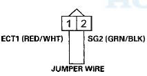
9. Connect MAF sensor/IAT sensor 5P connector terminals No. 1 and No. 2 with a jumper wire.
MAF SENSOR/IAT SENSOR 5P CONNECTOR
Wire side of female terminals
10. Turn the ignition switch to ON (II).
11. Clear the DTC with the HDS.
12. Check for Pending or Confirmed DTCs with the HDS Is DTC P0103 indicated? YES-Go to step 20.
NO-Go to step 13.
13. Turn the ignition switch to LOCK (0).
14. Replace the MAF sensor/IAT sensor (see page 11-199).
15. Reconnect all connectors.
16. Turn the ignition switch to ON (II).
17. Reset the ECM/PCM with the HDS.
18. Do the ECM/PCM idle learn procedure (see page 11-293).
19. Check for Pending or Confirmed DTCs with the HDS.
Is DTC P0103 indicated? YES-Check for poor connections or loose terminals at the MAF sensor/IAT sensor and the ECM/PCM, then go to step 1.
NO-Troubleshooting is complete. If any other Temporary DTCs or DTCs are indicated, go to the indicated DTCs troubleshooting.
20. Turn the ignition switch to LOCK (0).
21. Reconnect all connectors.
22. Update the ECM/PCM if it does not have the latest software (see page 11-203), or substitute a known-good ECM/PCM (see page 11-7).
23. Check for Pending or Confirmed DTCs with the HDS.
Is DTC P0103 indicated? YES
-Check for poor connections or loose terminals at the MAF sensor/IAT sensor and the ECM/PCM. If the ECM/PCM was updated, substitute a known-good ECM/PCM (see page 11 -7), then recheck. If the ECM/PCM was substituted, go to step 1.
NO
-lf the ECM/PCM was updated, troubleshooting is complete. If the ECM/PCM was substituted, replace the original ECM/PCM (see page 11-204). If any other Pending or Confirmed DTCs are indicated, go to the indicated DTCs troubleshooting.
DTC P0107:
MAP Sensor Circuit Low Voltage
NOTE: Before you troubleshoot record all freeze data and any on-board snapshot, and review the general troubleshooting information (see page 11-3).
1. Turn the ignition switch to ON (II).
2. Check the MAP SENSOR in the DATA LIST with the HDS.
Is about 3 kPa (1.0 inHg, 26 mmHg), or 0.23 V or less indicated? YES-Go to step 3.
NO-lntermittent failure, the system is OK at this time.
Check for poor connections or loose terminals at the MAP sensor and the ECM/PCM.
3. Turn the ignition switch to LOCK (0).
4. Disconnect the MAP sensor 3P connector.
5. Turn the ignition switch to ON (II).
6. Check the MAP SENSOR in the DATA LIST with the HDS.
Is about 3 kPa (1.0 inHg, 26 mmHg), or 0.23 V or less indicated? YES-Go to step 12.
NO-Go to step 7.
7. Measure the voltage between MAP sensor 3P connector terminals No. 1 and No. 3.
MAP SENSOR 3P CONNECTOR
Wire side of female terminals
Is there about 5 V? YES-Go to step 16.
NO-Go to step 8.
8. Turn the ignition switch to LOCK (0).
9. Jump the SCS line with the HDS.
10. Disconnect ECM/PCM connector C (49P).
11. Check for continuity between ECM/PCM connector terminal C13 and MAP sensor 3P connector terminal No. 1.
MAP SENSOR 3P CONNECTOR
Terminal side of female terminals
Is there continuity? YES
-Go to step 23.
NO
-Repair open in the wire between the ECM/PCM (C13) and the MAP sensor, then go to step 18.
12. Turn the ignition switch to LOCK (0).
13. Jump the SCS line with the HDS.
14. Disconnect ECM/PCM connector C (49P).
15. Check for continuity between MAP sensor 3P connector terminal No. 2 and body ground.
MAP SENSOR 3P CONNECTOR
Wire side of female terminals
Is there continuity? YES
-Repair short in the wire between the ECM/PCM (C11) and the MAP sensor, then go to step 18.
NO
-Go to step 23.
16. Turn the ignition switch to LOCK (0).
17. Replace the MAP sensor (see page 11 -199).
18. Reconnect all connectors.
19. Turn the ignition switch to ON (II).
20. Reset the ECM/PCM with the HDS.
21. Do the ECM/PCM idle learn procedure (see page 11-293).
22. Check for Pending or Confirmed DTCs with the HDS.
Is DTC P0107 indicated? YES-Check for poor connections or loose terminals at the MAP sensor and the ECM/PCM, then go to step 1.
NO-Troubleshooting is complete. If any other Pending or Confirmed DTCs are indicated, go to the indicated DTCs troubleshooting.
23. Reconnect all connectors.
24. Update the ECM/PCM if it does not have the latest software (see page 11-203), or substitute a known-good ECM/PCM (see page 11-7).
25. Check for Pending or Confirmed DTCs with the HDS.
Is DTC P0107 indicated? YES-Check for poor connections or loose terminals at the MAP sensor and the ECM/PCM. If the ECM/PCM was updated, substitute a known-good ECM/PCM (see page 11-7), then recheck. If the ECM/PCM was substituted, go to step 1.
NO-lf the ECM/PCM was updated, troubleshooting is complete. If the ECM/PCM was substituted, replace the original ECM/PCM (see page 11-204). If any other Pending or Ccnfirmed DTCs are Indicated, go to the indicated DTCs troubleshooting.
DTC P0108:
MAP Sensor Circuit High Voltage
NOTE: Before you troubleshoot, record all freeze data and any on-board snapshot, and review the general troubleshooting information (see page 11-3).
1. Turn the ignition switch to ON (II).
2. Check the MAP SENSOR in the DATA LIST with the HDS.
Is about 160 kPa (47.1 inHg, 1,197 mmHg), or 4.49 V or more Indicated? YES
-Go to step 3.
NO
-lntermittent failure, the system is OK at this time.
Check for poor connections or loose terminals at the MAP sensor and the ECM/PCM.
3. Turn the ignition switch to LOCK (0).
4. Disconnect the MAP sensor 3P connector.
5. Connect MAP sensor 3P connector terminals No. 2 and No. 3 with a jumper wire.
MAP SENSOR 3P CONNECTOR
Wire side of female terminals
6. Turn the ignition switch to ON (II).
7. Check the MAP SENSOR in the DATA LIST with the HDS.
Is about 160 kPa (47.1 inHg, 1,197 mmHg), or 4.49 V or more indicated? YES-Go to step 8.
NO-Go to step 18.
8. Remove the jumper wire from the MAP sensor 3P connector.
9. Measure the voltage between MAP sensor 3P connector terminals No. 1 and No. 3.
MAP SENSOR 3P CONNECTOR
Wire side of female terminals
Is there about 5 V? YES
-Go to step 14.
NO
-Go to step 10.
10. Turn the ignition switch to LOCK (0).
11. Jump the SCS line with the HDS.
12. Disconnect ECM/PCM connector C (49P).
13, Check for continuity between ECM/PCM connector terminal C14and MAP sensor 3P connector terminal No. 3.
MAP SENSOR 3P CONNECTOR
Terminal side of female terminals
Is there continuity? YES-Go to step 25.
NO-Repair open in the wire between the ECM/PCM (C14) and the MAP sensor, then go to step 20.
14. Turn the ignition switch to LOCK (0).
15. Jump the SCS line with the HDS.
16. Disconnect ECM/PCM connector C (49P).
17. Check for continuity between ECM/PCM connector terminal C11 and MAP sensor 3P connector terminal No. 2.
MAP SENSOR 3P CONNECTOR
Terminal side of female terminals
Is there continuity? YES-Go to step 25.
NO-Repair open in the wire between the ECM/PCM (C11) and the MAP sensor, then go to step 20.
18. Turn the ignition switch to LOCK (0).
19. Replace the MAP sensor (see page 11-199).
20. Reconnect all connectors.
21. Turn the ignition switch to ON (II).
22. Reset the ECM/PCM with the HDS.
23. Do the ECM/PCM idle learn procedure (see page 11-293).
24. Check for Pending or Confirmed DTCs with the HDS.
Is DTC P0108 indicated? YES-Check for poor connections or loose terminals at the MAP sensor and the ECM/PCM, then go to step 1.
NO-Troubleshooting is complete. If any other Pending or Confirmed DTCs are indicated, go to the indicated DTCs troubleshooting.
25. Reconnect all connectors.
26. Update the ECM/PCM If It does not have the latest software (see page 11-203), or substitute a known-good ECM/PCM (see page 11-7).
27. Check for Pending or Confirmed DTCs with the HDS.
Is DTC P0108 Indicated? YES-Check for poor connections or loose terminals at the MAP sensor and the ECM/PCM. If the ECM/PCM was updated, substitute a known-good ECM/PCM (see page 11-7), then recheck. If the ECM/PCM was substituted, go to step 1.
NO-lf the ECM/PCM was updated, troubleshooting is complete. If the ECM/PCM was substituted, replace the original ECM/PCM (see page 11-204). If any other Pending or Confirmed DTCs are indicated, go to the indicated DTCs troubleshooting.
DTC P0111:
IAT Sensor Circuit
Range/Performance Problem
NOTE: Before you troubleshoot, record all freeze data and any on-board snapshot, and review the general troubleshooting information (see page 11-3).
1. Check for poor connections or loose terminals at ECT sensors 1 and 2, and the MAF sensor/IAT sensor.
Are the connections and terminals OK? YES
-Go to step 2.
NO
-Repair the connections or terminals, then go to step 15.
2. Remove the MAF sensor/IAT sensor (see page 11-199).
3. Allow MAF sensor/IAT sensor to cool to the ambient temperature.
4. Note the ambient temperature.
5. Connect the MAF sensor/IAT sensor to its 5P connector, but do not install it.
6. Turn the ignition switch to ON (II).
7. Note the value of the IAT SENSOR quickly in the DATA LIST with the HDS.
8. Compare the value of the IAT SENSOR to the ambient temperature.
Does the value of the IAT SENSOR differ 5.4 Р’В°F (3 Р’В°C) or more from the ambient temperature? YES
-Go to step 13.
NO
-Go to step 9.
9. Disconnect the MAF sensor/IAT sensor from its 5P connector.
10. Using a heat gun, blow hot air on the MAF sensor/IAT sensor for a few seconds. Do not apply the heat longer than a few seconds or you will damage the sensor.
11. Connect the MAF sensor/IAT sensor to its 5P connector, but do not install it.
12. Check the IAT SENSOR in the DATA LIST with the HDS.
Does the IAT SENSOR change 63 Р’В°F (35 Р’В°C) or more? YES
-lntermittent failure, the system is OK at this time.
Check for poor connections or loose terminals at the MAF sensor/IAT sensor and the ECM/PCM.
NO
-Go to step 13.
13. Turn the ignition switch to LOCK (0).
14. Replace the MAF sensor/IAT sensor (see page 11-199).
15. Turn the ignition switch to ON (II).
16. Reset the ECM/PCM with the HDS.
17. Do the ECM/PCM idle learn procedure (see page 11-293).
18. Check for Pending or Confirmed DTCs with the HDS.
Is DTC P0111 indicated? YES
-Check for poor connections or loose terminals at the MAF sensor/IAT sensor and the ECM/PCM, then go to step 1.
NO
-Troubleshooting is complete. If any other Pending or Confirmed DTCs are indicated, go to the indicated DTCs troubleshooting.
DTC P0112:
IAT Sensor Circuit Low Voltage
NOTE: Before you troubleshoot, record all freeze data and any on-board snapshot, and review the general troubleshooting information (see page 11-3).
1. Turn the ignition switch to ON (II).
2. Check the IAT SENSOR in the DATA LIST with the HDS.
Is about 356 Р’В°F (180 Р’В°C) or more, or 0.08 V or less indicated? YES-Go to step 3.
NO-lntermittent failure, the system is OK at this time.
Check for poor connections or loose terminals at the MAF sensor/IAT sensor and the ECM/PCM.
3. Turn the ignition switch to LOCK (0).
4. Disconnect the MAF sensor/IAT sensor 5P connector.
5. Turn the ignition switch to ON (II).
6. Check the IAT SENSOR in the DATA LIST with the HDS.
Is about 356 Р’В° F (180 Р’В°C) or more, or 0.08 V or less indicated? YES-Go to step 7.
NO-Go to step 11.
7. Turn the ignition switch to LOCK (0).
8. Jump the SCS line with the HDS.
9. Disconnect ECM/PCM connector B (49P).
10. Check for continuity between MAF sensor/IAT sensor 5P connector terminal No. 5 and body ground.
MAF SENSOR/IAT SENSOR 5P CONNECTOR
Wire side of female terminals
Is there continuity? YES
-Repair short in the wire between the MAF sensor/IAT sensor and the ECM/PCM (B32), then go to step 13.
NO
-Go to step 18.
11. Turn the ignition switch to LOCK (0).
12. Replace the MAF sensor/IAT sensor (see page 11-199).
13. Reconnect all connectors.
14. Turn the ignition switch to ON (II).
15. Reset the ECM/PCM with the HDS.
16. Do the ECM/PCM idle learn procedure, (see page 11-293) 17. Check for Pending or Confirmed DTCs with the HDS.
Is DTC P0112 indicated? YES
-Check for poor connections or loose terminals at the MAF sensor/IAT sensor and the ECM/PCM, then go to step 1.
NO
-Troubleshooting is complete. If any other Pending or Confirmed DTCs are indicated, go to the indicated DTCs troubleshooting.
18. Reconnect all connectors.
19. Update the ECM/PCM if it does not have the latest software (see page 11 -203), or substitute a known-good ECM/PCM (see page 11-7).
20. Check for Pending or Confirmed DTCs with the HDS.
Is DTC P0112 indicated? YES
-Check for poor connections or loose terminals at the MAF sensor/IAT sensor and the ECM/PCM. If the ECM/PCM was updated, substitute a known-good ECM/PCM (see page 11-7), then recheck. If the ECM/PCM was substituted, go to step 1.
NO
-lf the ECM/PCM was updated, troubleshooting is complete. If the ECM/PCM was substituted, replace the original ECM/PCM (see page 11-204). If any other Pending or Confirmed DTCs are indicated, go to the indicated DTCs troubleshooting.
DTC P0113:
lAT Sensor Circuit High Voltage
NOTE: Before you troubleshoot record all freeze data and any on-board snapshot, and review the general troubleshooting information {see page 11-3).
1. Turn the ignition switch to ON (II).
2. Check the IAT SENSOR in the DATA LIST with the HDS.
Is about -40 Р’В°F (-40 Р’В°C) or less, or 4.92 V or more indicated? YES-Go to step 3.
NO-lntermittent failure, the system is OK at this time.
Check for poor connections or loose terminals at the MAF sensor/IAT sensor and the ECM/PCM.
3. Turn the ignition awitich to LOCK(0).
4. Disconnect the MAF sensor/IAT sensor 5P connector.
5. Connect MAF sensor/IAT sensor 5P connector terminals No. 4 and No. 5 with a jumper wire.
MAF SENSOR/IAT SENSOR 5P CONNECTOR
Wire side of female terminals
6. Turn the ignition switch to ON (II).
7. Check the IAT SENSOR in the DATA LIST with the HDS.
Is about -40 Р’В°F(-40 Р’В°C) or less, or 4.92 V or more indicated? YES-Go to step 8.
NO-Go to step 20.
8. Turn the ignition switch to LOCK (0).
9. Remove the jumper wire from the MAF sensor/IAT sensor 5P connector.
10. Turn the ignition switch to ON (II).
11. Measure the voltage between MAF sensor/IAT sensor 5P connector terminal No. 5 and body ground.
MAF SENSOR/IAT SENSOR 5P CONNECTOR
Wire side of female terminals
Is there about 5 V? YES
-Go to step 12.
NO
-Go to step 16.
12. Turn the ignition switch to LOCK (0).
13. Jump the SCS line with the HDS.
14. Disconnect ECM/PCM connector B (49P).
15. Check for continuity between MAF sensor/IAT sensor 5P connector terminal No. 4 and ECM/PCM connector terminal B34.
MAF SENSOR/IAT SENSOR 5P CONNECTOR
Terminal side of female terminals
Is there continuity? YES-Go to step 27.
NO-Repair open in the wire between the ECM/PCM (B34) and the MAF sensor/IAT sensor, then go to step 22.
16. Turn the ignition switch to LOCK (0).
17. Jump the SCS line with the HDS.
18. Disconnect ECM/PCM connector B (49P).
19. Check for continuity between MAF sensor/IAT sensor 5P connector terminal No. 5 and ECM/PCM connector terminal B32.
MAF SENSOR/IAT SENSOR 5P CONNECTOR
Terminal side of female terminals
Is there continuity? YES
-Go to step 27.
NO
-Repair open in the wire between the ECM/PCM (B32) and the MAF sensor/IAT sensor, then go to step 22.
20. Turn the ignition switch to LOCK (0).
21. Replace the MAF sensor/IAT sensor (see page 11-199).
22. Reconnect all connectors.
23. Turn the ignition switch to ON (II).
24. Reset the ECM/PCM with the HDS.
25. Do the ECM/PCM idle learn procedure (see page 11-293).
26. Check for Pending or Confirmed DTCs with the HDS.
Is DTC P0113 indicated? YES
-Check for poor connections or loose terminals at the MAF sensor/IAT sensor and the ECM/PCM, then go to step 1.
NO
-Troubleshooting is complete. If any other Pending or Confirmed DTCs are indicated, go to the indicated DTCs troubleshooting.
27. Reconnect all connectors.
28. Update the ECM/PCM if it does not have the latest software (see page 11-203), or substitute a known-good ECM/PCM (see page 11-7).
29. Check for Pending or Confirmed DTCs with the HDS.
Is DTC P0113 indicated? YES-Check for poor connections or loose terminals at the MAF sensor/IAT sensor and the ECM/PCM. If the ECM/PCM was updated, substitute a known-good ECM/PCM (see page 11-7), then recheck. If the ECM/PCM was substituted, go to step 1.
NO-lf the ECM/PCM was updated, troubleshooting is complete. If the ECM/PCM was substituted, replace the original ECM/PCM (see page 11-204). If any other Pending or Confirmed DTCs are indicated go to the indicated DTCs troubleshooting.
DTC P0116:
ECT Sensor 1 Circuit
Range/Performance Problem
NOTE: Before you troubleshoot, record all freeze data and any on-board snapshot, and review the general troubleshooting information (see page 11 -3).
1. Turn the ignition switch to ON (II).
2. Check ECT SENSOR 1 in the DATA LIST with the HDS.
Is about 176 Р’В°F (80 Р’В°C) or more, or 0.78 V or less indicated? YES
-Go to step 6.
NO
-Go to step 3.
3. Note the value of ECT SENSOR 1 in the DATA LIST with the HDS.
4. Start the engine. Hold the engine speed at 3,000 rpm without load (A/T in P or N, M/T in neutral) until the radiator fan comes on, then let it idle.
5. Check ECT SENSOR 1 in the DATA LIST with the HDS.
Does ECT SENSOR 1 change 18 Р’В°F (10 Р’В°C) or more? YES
-lntermittent failure, the system is OK at this time.
Check for poor connections or loose terminals at ECT sensor 1 and the ECM/PCM.
NO
-Go to step 11.
6. Note the value of ECT SENSOR 1 in the DATA LIST with the HDS.
7. Turn the ignition switch to LOCK (0).
8. Open the hood, and let the engine cool for 3 hours.
9. Turn the ignition switch to ON (II).
10. Check ECT SENSOR 1 in the DATA LIST with the HDS.
Does ECT SENSOR 1 change 18Р’В°F(10 Р’В°C) or more? YES
-lntermittent failure, the system is OK at this time.
Check for poor connections or loose terminals at ECT sensor 1 and the ECM/PCM.
NO
-Go to step 11.
11. Turn the ignition switch to LOCK (0).
12. Replace ECT sensor 1 (see page 11-200).
13. Turn the ignition switch to ON (II).
14. Reset the ECM/PCM with the HDS.
15. Do the ECM/PCM idle learn procedure (see page 11-293).
16. Check for Pending or Confirmed DTCs with the HDS.
Is DTC P0116 indicated? YES
-Check for poor connections or loose terminals at ECT sensor 1 and the ECM/PCM, then go to step 1.
NO
-Troubleshooting is complete. If any other Pending or Confirmed DTCs are indicated, go to the indicated DTCs troubleshooting.
DTC P0117
: ECT Sensor 1 Circuit Low Voltage
NOTE: Before you troubleshoot, record all freeze data and any on-board snapshot, and review the general troubleshooting information (see page 11-3).
1. Turn the ignition switch to ON (II).
2. Check ECT SENSOR 1 in the DATA LIST with the HDS.
Is about 356 Р’В°F (180 Р’В°C) or more, or 0.08 V or less indicated? YES
-Go to step 3.
NO
-lntermittent failure, the system is OK at this time.
Check for poor connections or loose terminals at ECT sensor 1 and the ECM/PCM.
3. Turn the ignition switch to LOCK (0).
4. Disconnect the ECT sensor 1 2P connector.
5. Turn the ignition switch to ON (II).
6. Check ECT SENSOR 1 in the DATA LIST with the HDS.
Is about 356 Р’В°F (180 Р’В°C) or more, or 0.08 V or less indicated? YES
-Go to step 7.
NO
-Go to step 11.
7. Turn the ignition switch to LOCK (0).
8. Jump the SCS line with the HDS.
9. Disconnect ECM/PCM connector B (49P).
10. Check for continuity between ECT sensor 1 2P connector terminal No. 1 and body ground.
ECT SENSOR 1 2P CONNECTOR
Wire side of female terminals
Is there continuity? YES
-Repair short in the wire between ECT sensor 1 and the ECM/PCM (B24), then go to step 13.
NO
-Go to step 18.
11. Turn the ignition switch to LOCK (0).
12. Replace ECT sensor 1 (see page 11-200).
13. Reconnect all connectors.
14. Turn the ignition switch to ON (II).
15. Reset the ECM/PCM with the HDS.
16. Do the ECM/PCM idle learn procedure (see page 11-293).
17. Check for Pending or Confirmed DTCs with the HDS.
Is DTC P0117 indicated? YES
-Check for poor connections or loose terminals at ECT sensor 1 and the ECM/PCM, then go to step 1.
NO
-Troubleshooting is complete. If any other Pending or Confirmed DTCs are indicated, go to the indicated DTCs troubleshooting.
18. Reconnect all connectors.
19. Update the ECM/PCM if it does not have the latest software (see page 11-203), or substitute a known-good ECM/PCM (see page 11-7).
20. Check for Pending or Confirmed DTCs with the HDS.
Is DTC P0117 indicated? YES
-Check for poor connections or loose terminals at ECT sensor 1 and the ECM/PCM. If the ECM/PCM was updated, substitute a known-good ECM/PCM (see page 11-7), then recheck. If the ECM/PCM was substituted, go to step 1.
NO
-lf the ECM/PCM was updated, troubleshooting is complete. If the ECM/PCM was substituted, replace thA nrinin.i ECM/rCm ;&ee page i 1-204). If any other Pending or Confirmed DTCs are indicated, go to the indicated DTCs troubleshooting.
DTC P0118:
ECT Sensor 1 Circuit High Voltage
NOTE: Before you troubleshoot, record all freeze data and any on-board snapshot, and review the general troubleshooting information (see page 11-3).
1. Turn the ignition switch to ON (II).
2. Check ECT SENSOR 1 in the DATA LIST with the HDS.
Is about -”40 В°F (-40 В°C) or less, or 4.92 V or more Indicated? YES
-Go to step 3.
NO
-lntermittent failure, the system is OK at this time.
Check for poor connections or loose terminals at ECT sensor 1 and the ECM/PCM.H 3. Turn the ignition switch to LOCK (0).
4. Disconnect the ECT sensor 1 2P connector.
5. Connect ECT sensor 1 2P connector terminals No. 1 and No. 2 with a jumper wire.
ECT SENSOR 1 2P CONNECTOR
Wire side of female terminals
6. Turn the ignition switch to ON (II).
7. Check ECT SENSOR 1 in the DATA LIST with the HDS.
Is about -40 Р’В°F (-40 Р’В°C) or less, or 4.92 Vor more indicated? YES-Go to step 8.
NO-Go to step 20.
8. Turn the ignition switch to LOCK (0).
9. Remove the jumper wire from the ECT sensor 1 2P connector.
10. Turn the ignition switch to ON (II).
11. Measure the voltage between ECT sensor 1 2P connector terminal No. 1 and body ground.
ECT SENSOR 1 2P CONNECTOR
Wire side of female terminals
Is there about 5 V? YES-Go to step 12.
NO-Go to step 16.
12. Turn the ignition switch to LOCK (0).
13. Jump the SCS line with the HDS.
14. Disconnect ECM/PCM connector B (49P).
15. Check for continuity between ECT sensor 1 2P connector terminal No. 2 and ECM/PCM connector terminal B34.
ECT SENSOR 1 2P CONNECTOR

Terminal side of female terminals
Is there continuity? YES
-Go to step 27.
NO
-Repair open in the wire between the ECM/PCM (B34) and ECT sensor 1, then go to step 22.
16. Turn the ignition switch to LOCK (0).
17. Jump the SCS line with the HDS.
18. Disconnect ECM/PCM connector B (49P).
19. Check for continuity between ECT sensor 1 2P connector terminal No. 1 and ECM/PCM connector terminal B24.
ECT SENSOR 1 2P CONNECTOR
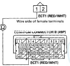
Terminal side of female terminals
Is there continuity? YES-Go to step 27.
NO-Repair open in the wire between the ECM/PCM (B24) and ECT sensor 1, then go to step 22.
20. Turn the ignition switch to LOCK (0).
21. Replace ECT sensor 1 (see page 11 -200).
22. Reconnect all connectors.
23. Turn the ignition switch to ON (II).
24. Reset the ECM/PCM with the HDS.
25. Do the ECM/PCM idle learn procedure (see page 11-293).
26. Check for Pending or Confirmed DTCs with the HDS.
Is DTC P0118 indicated? YES-Check for poor connections or loose terminals at ECT sensor 1 and the ECM/PCM, then go to step 1.
NO-Troubleshooting is complete. If any other Pending or Confirmed DTCs are indicated, go to the indicated DTCs troubleshooting.
27. Reconnect all connectors.
28. Update the ECM/PCM if it does not have the latest software (see page 11-203), or substitute a known-good ECM/PCM (see page 11-7).
29. Check for Pending or Confirmed DTCs with the HDS.
Is DTC P0118 indicated? YES-Check for poor connections or loose terminals at ECT sensor 1 and the ECM/PCM. If the ECM/PCM was updated, substitute a known-good ECM/PCM (see page 11-7), then recheck. If the ECM/PCM was substituted, go to step 1.
NO-lf the ECM/PCM was updated, troubleshooting is complete. If the ECM/PCM was substituted, replace the original ECM/PCM. If any other Pending or Confirmed DTCs are indicated, go to the indicated DTCs troubleshooting.
DTC P0125:
ECT Sensor 1 Malfunction/Slow Response
NOTE: Before you troubleshoot, record all freeze data and any on-board snapshot and review the general troubleshooting information (see page 11-3).
1. Start the engine, and let it idle for 5 minutes or more.
2. Check ECT SENSOR 1 In the DATA LIST with the HDS.
Is about 0Р’В°F (-18 Р’В°C) or less Indicated? YES
-Check for poor connections or loose terminals at ECT sensor 1, ECT sensor 2, and the ECM/PCM. If the connections and terminal are OK, replace ECT sensor 1 (see page 11-200), then go to step 9.
NO
-Go to step 3.
3. Turn the ignition switch to LOCK (0).
4. Allow the engine to cool to 104 Р’В°F (40 Р’В°C) or less.
5. Start the engine, and let it idle until ECT SENSOR 1goes up to about 158 Р’В°F (70 Р’В°C).
Does ECT SENSOR 2 also read about 158 Р’В°F (70 Р’В°C)? YES-Go to step 6.
NO-lntermittent failure, the system is OK at this time.
Check for poor connections or loose terminals at ECT sensor 1, ECT sensor 2, and the ECM/PCM.
6. Check the thermostat (see page 10-4).
Is the thermostat OK? YES-Check for poor connections or loose terminals at ECT sensor 1, ECT sensor 2, and the ECM/PCM. If the connections and terminal are OK, replace ECT sensor 1 (see page 11-200), then go to step 7.
NO-Replace the thermostat (see page 10-8), then go to step 7.
7. Turn the ignition switch to ON (II).
8. Reset the ECM/PCM with the HDS.
9. Turn the ignition switch to LOCK (0).
10. Allow the engine to cool to 104 Р’В°F (40 Р’В°C) or less.
11. Start the engine, and let it idle until ECT SENSOR 1 goes up to about 158 Р’В°F (70 Р’В°C).
Does ECT SENSOR 2 also read about 158 Р’В°F (70 Р’В°C)? YES-Go to step 1 and recheck.
NO-Troubleshooting is complete.
DTC P0128:
Cooling System Malfunction
NOTE: Before you troubleshoot, record all freeze data and any on-board snapshot, and review the general troubleshooting information (see page 11-3).
1. Turn the ignition switch to ON (II).
2. Clear the DTC with the HDS.
3. Make sure the blower switch is off.
4. Check the FAN CTRL in the DATA LIST with the HDS.
Is it OFF? YES
-Go to step 5.
NO
-Wait until the FAN CTRL is off, then go to step 5.
5. Check the radiator fan operation.
Does the radiator fan keep running? YES
-Check the radiator fan circuit (see page 10-26), and the radiator fan relay (see page 22-93). If the circuits and the relay are OK, go to step 19.
NO
-Go to step 6.
6. Let the engine cool until the coolant temperature is 104 Р’В°F (40 Р’В°C) or less.
7. Note the value of ECT SENSOR 1 and ECT SENSOR 2 in the DATA LIST with the HDS.
8. Start the engine, and let it idle.
9. Let the engine idle until ECT SENSOR 1 goes up 41 Р’В°F (23 Р’В°C) or more from the recorded temperature.
10. Check ECT SENSOR 2 in the DATA LIST with the HDS.
11. Compare the recorded value of ECT SENSOR 2 and the present value of ECT SENSOR 2.
Did the temperature rise 14 Р’В°F (8 Р’В°C) or more? YES
-Test the thermostat (see page 10-4), then go to step 12.
NO
-lntermittent failure, the system is OK at this time.
Check for poor connections or loose terminals at ECT sensor 1, ECT sensor 2, and the ECM/PCM.
12. Turn the ignition switch to ON (11).
13. Reset the ECM/PCM with the HDS.
14. Let the engine cool until the coolant temperature is between 21 Р’В°F ( - 6 Р’В°C) and 104 Р’В°F (40 Р’В°C).
15. Do the ECM/PCM idle learn procedure (see page 11-293).
18. Test-drive at a steady speed between 15-”75 mph (24-120 km/h) for 10 minutes.
17. Check for Pending or Confirmed DTCs with the HDS.
Is DTC P0128 indicated? YES
-Check the cooling system, then go to step 19.
NO
-Go to step 18.
Does the screen indicate PASSED? YES-Troubleshooting is complete. If any other Pending or Confirmed DTCs were indicated in step 17, go to the indicated DTCs troubleshooting.
NO-lf the screen indicates FAILED, check the cooling system, then go to step 19. If the screen indicates NOT COMPLETED, go to step 14.
19. Update the ECM/PCM if it does not have the latest software (see page 11-203), or substitute a known-good ECM/PCM (see page 11-7).
20. Let the engine cool until the coolant temperature is between 21 Р’В°F ( - 6 Р’В°C) and 104 Р’В°F (40 Р’В°C).
21. Start the engine. Hold the engine speed at 3,000 rpm without load (A/T in P or N, M/T in neutral) until the radiator fan comes on, then let it idle.
22. Test-drive at a steady speed between 15-”75 mph (24-120 km/h) for 10 minutes.
23. Check for Pending or Confirmed DTCs with the HDS.
is DTC P0128 indicated? YES-Check for poor connections or loose terminals at ECT sensor 1, ECT sensor 2, and the ECM/PCM. If the ECM/PCM was updated, substitute a known-good ECM/PCM (see page 11-7), then go to step 20. If the ECM/PCM was substituted, go to step 1.
NO-Go to step 24.
24. Monitor the OBD STATUS for DTC P0128 in the DTCs MENU with the HDS.
Does the screen indicate PASSED? YES
-lf the ECM/PCM was updated, troubleshooting is complete. If the ECM/PCM was substituted, replace the original ECM/PCM (see page 11-204). If any other Pending or Confirmed DTCs were indicated in step 23, go to the indicated DTCs troubleshooting.- NO
-lf the screen indicates FAILED, check for poor connections or loose terminals at ECT sensor 1, ECT sensor 2, and the ECM/PCM. If the ECM/PCM was updated, substitute a known-good ECM/PCM (see page 11-7), then go to step 20. If the ECM/PCM was substituted, go to step 1. If the screen indicates NOT COMPLETED, go to step 20.
DTC P0133:
A/F Sensor (Sensor 1)
Malfunction/Slow Response
NOTE: Before you troubleshoot record all freeze data and any on-board snapshot, and review the general troubleshooting information (see page 11-3).
1. Turn the ignition switch to ON (II).
2. Clear the DTC with the HDS.
3. Start the engine. Hold the engine speed at 3,000 rpm without load (A/T in P or N, M/T in neutral) until the radiator fan comes on, then let it idle.
4. Test-drive under these conditions:
- Engine coolant temperature (ECT SENSOR 1) above 158 Р’В°F (70 Р’В°C)
- A/Tin D, M/T in 3rd or 4th
- Drive the vehicle at 25 mph (40 km/h) or less for 5 minutes, then drive at a steady speed about 32 mph (52 km/h) or more
5. Monitor the OBD STATUS for DTC P0133 in the DTCs MENU with the HDS.
Does the screen indicate FAILED? YES-Go to step 6.
NO-lf the screen indicates PASSED, intermittent failure, the system is OK at this time. Check for poor connections or loose terminals at the A/F sensor (Sensor 1) and the ECM/PCM. If the screen indicates EXECUTING, keep driving until a result comes on. If the screen indicates OUT OF CONDITION or NOT COMPLETED, go to step 3 and recheck.
6. Turn the ignition switch to LOCK (0).
7. Replace the A/F sensor (Sensor 1) (see page 11-197).
8. Turn the ignition switch to ON (II).
9. Reset the ECM/PCM with the HDS.
10. Do the ECM/PCM idle learn procedure (see page 11-293).
11. Start the engine. Hold the engine speed at 3,000 rpm without load (A/T in P or N, M/T in neutral) until the radiator fan comes on, then let it idle.
12. Test-drive under these conditions:
- Engine coolant temperature (ECT SENSOR 1) above 158Р’В°F(70 Р’В°C)
- A/Tin D, in 3rd or4th
- Drive the vehicle at 25 mph (40 km/h) or less for 5 minutes, then drive at a steady speed about 32 mph (52 km/h) or more
Check for Pending or Confirmed DTCs with the HDS.
Is DTC P0133 indicated? YES
-Check for poor connections or loose terminals at the A/F sensor (Sensor 1) and the ECM/PCM, then go to step 1.
NO
-Go to step 14.
14. Monitor the OBD STATUS for DTC P0133 in the DTCs MENU with the HDS.
Does the screen indicate PASSED? YES
-Troubleshooting is complete. If any other Pending or Confirmed DTCs were indicated in step 13, go to the indicated DTCs troubleshooting.
NO
-lf the screen indicates FAILED, check for poor connections or loose terminals at the A/F sensor (Sensor 1) and the ECM/PCM, then go to step 1. If the screen indicates EXECUTING, keep driving until a result comes on. If the screen indicates OUT OF CONDITION or NOT COMPLETED, go to step 11.
DTC P0134:
A/F Sensor (Sensor 1) Heater System Malfunction
NOTE: - Before you troubleshoot, record all freeze data and any on-board snapshot, and review the general troubleshooting information (see page 11-3).
- If the vehicle was out of fuel and the engine stalled before this DTC was stored, refuel and clear the DTC with the HDS.
- If DTC P0135 is stored at the same time as DTC P0134, troubleshoot DTC P0135 first, then recheck for DTC P0134.
1. Turn the ignition switch to ON (II).
2. Clear the DTC with the HDS.
3. Start the engine, and let it idle without load (A/T in P or N, M/T in neutral) until the radiator fan comes on.
4. Check for Pending or Confirmed DTCs with the HDS.
Is DTC P0134 indicated? YES-Go to step 5.
NO-lntermittent failure, the system is OK at this time.
Check for poor connections or loose terminals at the A/F sensor (Sensor 1), the PGM-FI subrelay, and the ECM/PCM.
5. Turn the ignition switch to LOCK (0).
6. Replace the A/F sensor (Sensor 1) (see page 11 -197).
7. Turn the ignition switch to ON (II).
8. Reset the ECM/PCM with the HDS.
9. Do the ECM/PCM idle learn procedure (see page 11-293).
10. Check for Pending or Confirmed DTCs with the HDS.
Is DTC P0134 indicated? YES
-Check for poor connections or loose terminals at the A/F sensor (Sensor 1), the PGM-FI subrelay, and the ECM/PCM, then go to step 1.
NO
-Go to step 11.
11. Monitor the OBD STATUS for DTC P0134 in the DTCs MENU with the HDS.
Does the screen indicate PASSED? YES
-Troubleshooting is complete. If any other Pending or Confirmed DTCs were indicated in step 10, go to the indicated DTCs troubleshooting.
NO
-lf the screen indicates FAILED, check for poor connections or loose terminals at the A/F sensor (Sensor 1), the PGM-FI subrelay, and the ECM/PCM, then go to step 1. If the screen indicates NOT COMPLETED, keep idling until a result comes on.
DTC P0135:
A/F Sensor (Sensor 1) Heater
Circuit Malfunction
NOTE; Before you troubleshoot record all freeze data and any on-board snapshot and review the general troubleshooting information (see page 11-3).
1. Turn the ignition switch to ON (II).
2. Clear the DTC with the HDS.
3. Start the engine. Hold the engine speed at 3,000 rpm without load (A/T in P or N, M/T in neutral) until the radiator fan comes on, then let it idle.
4. Check for Pending or Confirmed DTCs with the HDS.
Is DTC P0135 indicated? YES-Go to step 5.
NO-lntermittent failure, the system is OK at this time.
Check for poor connections or loose terminals at the A/F sensor (Sensor 1), the PGM-FI subrelay, and the ECM/PCM.
5. Turn the ignition switch to LOCK (0).
6. Check the No. 14 FI SUB (15 A) fuse in the under-hood fuse/relay box.
Is the fuse OK? YES-Go to step 7.
NO-Go to step 19.
7. Remove the PGM-FI subrelay (A) from the under-hood fuse/relay box.
8. Test the PGM-FI subrelay (see page 22-93).
Is the relay OK? YES-Go to step 9.
NO-Replace the PGM-FI subrelay, then go to step 24.
9. Disconnect the A/F sensor (Sensor 1) 4P connector.
10. At the sensor side, measure the resistance between A/F sensor (Sensor 1) 4P connector terminals No. 3 and No. 4.
A/F SENSOR (SENSOR 1) 4P CONNECTOR

Terminal side of male terminals
Is there 2.0-”2.7 O at room temperature? YES
-Go to step 11.
NO
-Go to step 23.
11. At the sensor side, check for continuity between A/F sensor (Sensor 1) 4P connector terminals No. 2 and No. 3, and between terminals No. 2 and No. 4 individually.
A/F SENSOR (SENSOR 1) 4P CONNECTOR
Terminal side of male terminals
Is there continuity? YES-Go to step 23.
NO-Go to step 12.
12. Jump the SCS line with the HDS.
13. Disconnect ECM/PCM connector C (49P).
14. Check for continuity between ECM/PCM connector terminal C9 and body ground.
Terminal side of female terminals
Is there continuity? YES-
Repair short in the wire between the ECM/PCM (C9) and the A/F sensor (Sensor 1), then go to step 24.
NO
-Go to step 15.
15. Check for continuity between A/F sensor (Sensor 1) 4P connector terminal No. 4 and ECM/PCM connector terminal C9.
A/F SENSOR (SENSOR 1) 4P CONNECTOR
Is there continuity? YES-Go to step 16.
NO-Repair open in the wire between the ECM/PCM (C9) and the A/F sensor (Sensor 1), then go to step 24.
16. Check for continuity between A/F sensor (Sensor 1) 4P connector terminal No. 3 and PGM-FI subrelay 4P connector terminal No. 2.
A / F SENSOR (SENSOR 1) 4P CONNECTOR
Terminal side of female terminals
Is there continuity? YES
-Go to step 17.
NO
-Repair open in the wire between the A/F sensor (Sensor 1) and the PGM-FI subrelay, then goto step 24.
17. Disconnect ECM/PCM connector A (49P).
18. Check for continuity between PGM-FI subrelay 4P connector terminal No. 3 and ECM/PCM connector terminal A22.
PGM-FI SUBRELAY 4P CONNECTOR
Terminal side of female terminals
Is there continuity? YES
-Go to step 30.
NO
-Repair open in the wire between the ECM/PCM (A22) and the PGM-FI subrelay, then go to step 24.
19. Remove the PGM-FI subrelay (A) from the under-hood fuse/relay box.
20. Disconnect the A/F sensor (Sensor 1) 4P connector.
21. Disconnect the EVAP canister vent shut valve 2P connector.
22. Check for continuity between A/F sensor (Sensor 1) 4P connector terminal No. 3 and body ground.
A/F SENSOR (SENSOR 1) 4P CONNECTOR
Wire side of female terminals
Is there continuity? YES
-Repair short in the wire between the PGM-FI subrelay, the A/F sensor (Sensor 1), and the EVAP canister vent shut valve. Also replace the No. 14 FI SUB (15 A) fuse, then go to step 24.
NO
-Checkthe under-hood fuse/relay box, and replace it if needed (see page 22-85), then go to step 24.
23. Replace the A/F sensor (Sensor 1) (see page 11-197).
24. Reconnect all connectors.
25. Turn the ignition switch to ON (II).
26. Reset the ECM/PCM with the HDS.
27. Do the ECM/PCM idle learn procedure (see page 11-293).
28. Check for Pending or Confirmed DTCs with the HDS.
Is DTC P0135 indicated? YES
-Check for poor connections or loose terminals at the A/F sensor (Sensor 1), the PGM-FI subrelay, and the ECM/PCM, then go to step 1.
NO
-Go to step 29.
29. Monitor the OBD STATUS for DTC P0135 in the DTCs MENU with the HDS.
Does the screen indicate PASSED? YES-Troubleshooting is complete. If any other Pending or Confirmed DTCs were indicated in step 28, go to the indicated DTCs troubleshooting.
NO-lf the screen indicates FAILED, check for poor connections or loose terminals at the A/F sensor (Sensor 1), the PGM-FI subrelay, and the ECM/PCM, then go to step 1. If the screen indicates NOT COMPLETED, keep idling until a result comes on.
30. Reconnect all connectors.
31. Update the ECM/PCM if it does not have the latest software (see page 11 -203), or substitute a known-good ECM/PCM (see page 11-7).
32. Start the engine, and let it idle.
33. Check for Pending or Confirmed DTCs with the HDS.
Is DTC P0135 indicated? YES
-Check for poor connections or loose terminals at the A/F sensor (Sensor 1), the PGM-FI subrelay, and the ECM/PCM. If the ECM/PCM was updated, substitute a known-good ECM/PCM (see page 11-7), then go to step 32. If the ECM/PCM was substituted, go to step 1.
NO
-Go to step 34.
34. Monitor the OBD STATUS for DTC P0135 in the DTCs MENU with the HDS.
Does the screen indicate PASSED?
YES-
lf the ECM/PCM was updated, troubleshooting is complete. If the ECM/PCM was substituted, replace the original ECM/PCM (see page 11-204). If any other Pending or Confirmed DTCs were indicated in step 33, go to the indicated DTCs troubleshooting.
NO
-lf the screen indicates FAILED, check for poor connections or loose terminals at the A/F sensor (Sensor 1), the PGM-FI subrelay, and the ECM/PCM. If the ECM/PCM was updated, substitute a known-good ECM/PCM (see page 11-7), then go to step 32. If the ECM/PCM was substituted, go to step 1. If the screen indicates NOT COMPLETED, keep idling until a result comes on.
DTC P0137:
Secondary H02S (Sensor 2) Circuit Low Voltage
NOTE: Before you troubleshoot, record all freeze data and any oh-board snapshot, and review the general troubleshooting information (see page 11-3).
1. Turn the ignition switch to ON (II).
2. Clear the DTC with the HDS.
3. Start the engine. Hold the engine speed at 3,000 rpm without load (A/T in P or N, M/T in neutral) until the radiator fan comes on, then let it idle.
4. Check H02S S2 in the DATA LIST with the HDS.
Does the voltage stay at 0.05 V or less? YES
-Go to step 5.
NO
-lntermittent failure, the system is OK at this time.
Check for poor connections or loose terminals at secondary H02S (Sensor 2) and the ECM/PCM.
5. Turn the ignition switch to LOCK (0).
6. Disconnect the secondary H02S (Sensor 2) 4P connector.
7. Turn the ignition switch to ON (II).
8. Check H02S S2 in the DATA LIST with the HDS.
Does the voltage stay at 0.05 V or less? YES-
Go to step 9.
NO
-Go to step 13.
9. Turn the ignition switch to LOCK (0).
10. Jump the SCS line with the HDS.
11. Disconnect ECM/PCM connector B (49P).
12. Check for continuity between secondary H02S (Sensor 2) 4P connector terminal No. 2 and body ground.
SECONDARY H02S (SENSOR 2) 4P CONNECTOR
Terminal side of male terminals
Is there continuity? YES
-Repair short in the wire between the ECM/PCM (B36) and secondary H02S (Sensor 2), then go to step 15.
NO
-Go to step 23.
13. Turn the ignition switch to LOCK (0).
14. Replace secondary H02S (Sensor 2) (see page 11-197).
15. Reconnect all connectors.
16. Turn the ignition switch to ON (II).
17. Reset the ECM/PCM with the HDS.
18. Do the ECM/PCM idle learn procedure, (see page 11-293) 19. Start the engine, and let it idle without load (A/T in P or N, M/T in neutral) until the radiator fan comes on.
20. Test-drive under these conditions: - Engine coolant temperature (ECT SENSOR 1) above 158В°F(70 В°C) - A/T in D, M/T in 4th - Engine speed between 1,500-”3,000 rpm - Drive about 1 minute or more 21. Check for Pending or Confirmed DTCs with the HDS.
Is DTC P0137 indicated? YES
-Check for poor connections or loose terminals at secondary H02S (Sensor 2) and the ECM/PCM, then go to step 1.
NO
-Go to step 22.
22. Monitor the OBD STATUS for DTC P0137 in the DTCs MENU with the HDS.
Does the screen indicate PASSED? YES
-Troubleshooting is complete. If any other Pending or Confirmed DTCs were indicated in step 21, go to the indicated DTCs troubleshooting.
NO
-lf the screen indicates FAILED, check for poor connections or loose terminals at secondary H02S (Sensor 2) and the ECM/PCM, then go to step 1. If the screen indicates EXECUTING, keep driving until a result comes on. If the screen indicates OUT OF CONDITION or NOT COMPLETED, go to step 19.
23. Reconnect all connectors.
24. Update the ECM/PCM if it does not have the latest software (see page 11-203), or substitute a known-good ECM/PCM (see page 11-7).
25. Start the engine, and let it idle without load (A/T in P or N, M/T in neutral) until the radiator fan comes on.
26. Test-drive under these conditions:
- Engine coolant temperature (ECT SENSOR 1) above 158 Р’В°F (70 Р’В°C)
- A/T in D, M/T in 4th
- Engine speed between 1,500-”3,000 rpm
- Drive 1 minute or more
27. Check for Pending or Confirmed DTCs with the HDS.
Is DTC P0137 indicated? YES-
Check for poor connections or loose terminals at secondary H02S (Sensor 2) and the ECM/PCM. If the ECM/PCM was updated, substitute a known-good ECM/PCM (see page 11-7), then go to step 25. If the ECM/PCM was substituted, go to step 1.
NO-
Go to step 28.
28. Monitor the OBD STATUS for DTC P0137 in the DTCs MENU with the HDS.
Does the screen indicate PASSED? YES-
lf the ECM/PCM was updated, troubleshooting is complete. If the ECM/PCM was substituted, replace the original ECM/PCM (see page 11-204). If any other Pending or Confirmed DTCs were indicated in step 27, go to the indicated DTCs troubleshooting-^ NO
-lf the screen indicates FAILED, check for poor connections or loose terminals at secondary H02S (Sensor 2) and the ECM/PCM. If the ECM/PCM was updated, substitute a known-good ECM/PCM (see page 11 -7), then go to step 25. If the ECM/PCM was substituted, go to step 1. If the screen indicates EXECUTING, keep driving until a result comes on. If the screen indicates OUT OF CONDITION or NOT COMPLETED, go to step 25.
DTC P0138:
Secondary H02S (Sensor 2) Circuit High Voltage
NOTE: Before you troubleshoot, record all freeze data and any on-board snapshot, and review the general troubleshooting information (see page 11-3).
1. Turn the ignition switch to ON (II).
2. Clear the DTC with the HDS.
3. Start the engine. Hold the engine speed at 3,000 rpm without load (A/T in P or N, M/T in neutral) until the radiator fan comes on, then let it idle.
4. Check H02S S2 in the DATA LIST with the HDS.
Does the voltage stay at 1.27 V or more? YES
-Go to step 5.
NO
-lntermittent failure, the system is OK at this time.
Check for poor connections or loose terminals at secondary H02S (Sensor 2) and the ECM/PCM.
5. Turn the ignition switch to LOCK (0).
6. Disconnect the secondary H02S

 F-CAN Circuit Troubleshooting
1. Turn the ignition switch to LOCK (0).
2. Jump the SCS line with the HDS.
3. Disconnect ECM/PCM connector A (49P).
4. Measure the resistance between ECM/PCM connector
terminals A3 and A4.
...
See also:
Honda Accord 2013-2026 Owner's Manual
...
Playing Internet Radio
Connect a compatible phone through Bluetooth®.
You can also connect the phone using your dock connector to the USB port.
Make sure the audio setting is correct for the connection type.
Select ...
DTC Troubleshooting Index
NOTE: Record all DTCs, and sort them by DTC type using the DTC
troubleshooting index, then troubleshoot the DTC(s)
in this order:
• Battery voltage DTCs
• Internal error DTCs
• Lo ...