 Honda Accord: DTC Troubleshooting
PTC 11 -1x { " x " can be 0 ,2 thru 3 or A thru F):
Open io the Driver's Airbag First Inflator
DTC 11-4x ("x" can be 0,2 thru 9 or A thru F):
Open in the Driver's Airbag Second Inflator
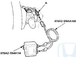
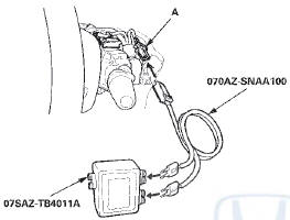
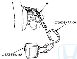
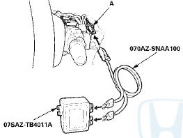
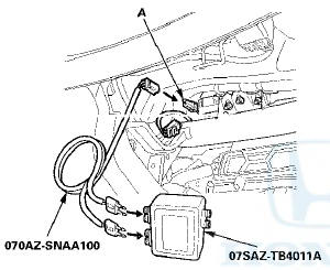
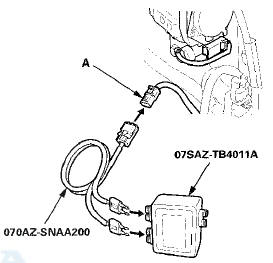
Special Tools Required
•SRS Inflator Simulator 07SAZ-TB4011A
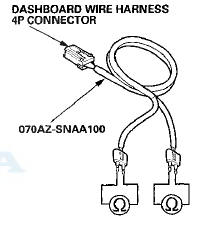
• SRS Simulator Lead J 070AZ-SNAA100
NOTE: • Before doing this troubleshooting procedure, review SRS Precautions and Procedures (see page 24-25), General Troubleshooting Information (see page 24-36), a n d Battery Terminal Disconnection and Reconnection (see page 22-91).
• 2-door: Before replacing the SRS unit, check the SRS unit software version with the HDS. If the software version is not the latest, update the SRS unit software (see page 24-39), and retest.
1. Clear the DTC with the HDS (see page 24-38).
2. Turn the ignition switch to ON (II), then wait for 10 seconds.
3. Check for DTCs with the HDS (see page 24-37).
Is DTC 11-1x or 11-4x indicated? YES
-Go to step 4.
NO
-lntermittent failure, the system is OK at this time.
Go to Troubleshooting Intermittent Failures (see page 24-38). If another DTC is indicated, troubleshoot the DTC.
4. Turn the ignition switch to LOCK (0).
5. Disconnect the negative cable from the battery, then wait at least 3 minutes.
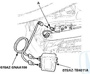
6. Disconnect the driver's airbag 4P connector (A) from the cable reel 4P connector.
7. Connect the SRS inflator simulator (2 Q connectors) and simulator lead J to the cable reel.
8. Reconnect the negative cable to the battery.
9. Clear the DTC with the HDS (see page 24-38).
10. Check for DTCs with the HDS (see page 24-37).
Is DTC 11-1x or 11-4x indicated? YES
-Go to step 11.
NO
-Open in the driver's airbag first or second inflator; replace the driver's airbag (see page 24-211), then clear the DTC.
11. Turn the ignition switch to LOCK (0).
12. Disconnect the negative cable from the battery, then wait at least 3 minutes.
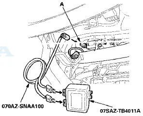
13. Remove the column cover (see page 20-181), then disconnect the dashboard wire harness 4P connector (A) from the cable reel 4P connector.
14. Connect the SRS inflator simulator (2 O connectors) and the simulator lead J to the dashboard wire harness.
15. Reconnect the negative cable to the battery.
16. Clear the DTC with the HDS (see page 24-38).
17. Check for DTCs with the HDS (see page 24-37).
Is DTC 11-1x or 11-4x indicated? YES
-Go to step 18.
NO
-Open in the cable reel; replace the cable reel (see page 24-225), then clear the DTC.
18. Turn the ignition switch to LOCK (0).
19. Disconnect the negative cable from the battery, then wait at least 3 minutes.
20. Disconnect SRS unit connector A (39P) from the SRS unit (see step 11 on page 24-36).
21. Disconnect the SRS inflator simulator from the SRS simulator lead. Do not disconnect the simulator lead from the dashboard wire harness 4P connector.
22. Measure the resistance between the terminals of both
SRS simulator leads. There should be less than 1.0 .
.
Is the resistance as specified?
YES
-Faulty SRS unit or poor connection at SRS unit connector A (39P) and the SRS unit. Check the connection between the connector and the SRS unit.
If the connection is OK, replace the SRS unit (see page 24-228).
NO
-Open in the dashboard wire harness; replace the dashboard wire harness, then clear the DTC.
DTC 11-11:
Short to Another Airbag Inflator in the Driver's Airbag First Inflator (4-door)
NOTE: Before doing this troubleshooting procedure, review SRS Precautions and Procedures (see page 24-25), General Troubleshooting Information (see page 24-36), and Battery Terminal Disconnection and Reconnection (see page 22-91).
1. Clear the DTC with the HDS (see page 24-38).
2. Turn the ignition switch to ON (II), then wait for 10 seconds.
3. Check for DTCs with the HDS (see page 24-37).
Is DTC 11-11 indicated? YES
-Go to step 4.
NO
-lntermittent failure, the system is OK at this time.
Go to Troubleshooting Intermittent Failures (see page 24-38). If another DTC is indicated, troubleshoot the DTC.
4. Check for DTCs with the HDS (see page 24-37).
Is DTC 12-11 or 12-41 indicated with DTC 11-11? YES
-Go to step 5.
NO
-Go to step 9.
5. Turn the ignition switch to LOCK (0).
6. Disconnect the negative cable from the battery, then wait at least 3 minutes.
7. Disconnect SRS unit connector A (39P) from the SRS unit (see step 11 on page 24-36).
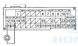
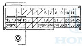
8. Check for continuity between the terminals of SRS unit connector A (39P) according to the table. There should be no continuity.
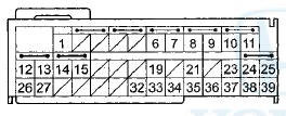
SRS UNIT CONNECTOR A (39P)
Wire side of female terminals
Is there continuity? YES
-Short to another wire in the dashboard wire harness; replace the dashboard wire harness, then clear the DTC.
NO-
Faulty SRS unit; replace the SRS unit (see page 24-228).
9. Turn the ignition switch to LOCK (0).
10. Disconnect the negative cable from the battery, then wait at least 3 minutes.
11. Disconnect SRS unit connector A (39P) from the SRS unit (see step 11 on page 24-36).
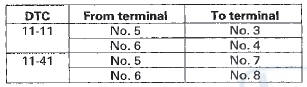
12. Check for continuity between SRS unit connector A (39P) terminals No. 3 and No. 7, and No. 4 and No. 8, respectively. There should be no continuity.
SRS UNIT CONNECTOR A (39P)
Wire side of female terminals
Is there continuity? YES
-Go to step 13.
NO
-Faulty SRS unit; replace the SRS unit (see page 24-228).
13. Disconnect the driver's airbag 4P connector from the cable reel 4P connector (see step 2 on page 24-33).
14. Check for continuity between SRS unit connector A (39P) terminals No. 3 and No. 7, and No. 4 and No. 8, respectively. There should be no continuity.
SRS UNIT CONNECTOR A (39P)
Wire side of female terminals
Is there continuity? YES
-Go to step 15.
NO
-Faulty driver's airbag; replace the driver's airbag (see page 24-211), then clear the DTC.
15. Remove the column cover (see page 20-181), then disconnect the dashboard wire harness 4P connector (A) from the cable reel 4P connector.

16. Check for continuity between SRS unit connector A (39P) terminals No. 3 and No. 7, and No. 4 and No. 8, respectively. There should be no continuity.
SRS UNIT CONNECTOR A (39P)
Wire side of female terminals
Is there continuity? YES
-Short to another wire in the dashboard wire harness; replace the dashboard wire harness, then clear the DTC.
NO-
Short in the cable reel; replace the cable reel (see page 24-225), then clear the DTC.
DTC 11-41:
Short to Another Airbag Inflator in the Driver's Airbag Second Inflator (4-door)
NOTE: Before doing this troubleshooting procedure, review SRS Precautions and Procedures (see page 24-25), General Troubleshooting Information (see page 24-36), and Battery Terminal Disconnection and Reconnection (see page 22-91).
1. Clear the DTC with the HDS (see page 24-38).
2. Turn the ignition switch to ON (II), then wait for 10 seconds.
3. Check for DTCs with the HDS (see page 24-37).
Is DTC 11-41 indicated? YES
-Go to step 4.
NO
-lntermittent failure, the system is OK at this time.
Go to Troubleshooting Intermittent Failures (see page 24-38). If another DTC is indicated, troubleshoot the DTC.
4. Check for DTCs with the HDS (see page 24-37).
Is DTC 12-11 or 12-41 indicated with DTC 11-41? YES
-Go to step 5.
NO
-Short to another wire in the dashboard wire harness; replace the dashboard wire harness, then clear the DTC.
5. Turn the ignition switch to LOCK (0).
6. Disconnect the negative cable from the battery, then wait at least 3 minutes.
7. Disconnect SRS unit connector A (39P) from the SRS unit (see step 11 on page 24-36).
8. Check for continuity between the terminals of SRS unit connector A (39P) according to the table. There should be no continuity.
SRS UNIT CONNECTOR A (39P)
Wire side of female terminals
Is there continuity? YES
-Short to another wire in the dashboard wire harness; replace the dashboard wire harness, then clear the DTC.
NO-
Faulty SRS unit; replace the SRS unit (see page 24-228).
DTC 11-3x { " x " can be i thru 9 or A thru F):
Short to Another Wire or Decreased Resistance in the Driver's Airbag First Inflator
DTC 11-6x ("x" can be 0 thru 9 or A thru F):
Short to Another Wire or Decreased Resistance in the Driver's Airbag Second Inflator
Special Tools Required
* SRS Inflator Simulator 07SAZ-TB4011A
• SRS Simulator Lead J 070AZ-SNAA100
•SRS Short Canceller 070AZ-SAA0100
NOTE: • Before doing this troubleshooting procedure, review General Troubleshooting Information (see page 24-36), and Battery Terminal Disconnection and Reconnection (see page 22-91), • 2-door: Before replacing the SRS unit, check the SRS unit software version with the HDS. Ifthe software version is not the latest, update the SRS unit software (see page 24-39), and retest.
1. Clear the DTC with the HDS (see page 24-38).
2. Turn the ignition switch to ON (II), then wait for 10 seconds.
3. Check for DTCs with the HDS (see page 24-37).
Is DTC 11-3x or 11 -6x indicated? YES
-Go to step 4.
NO
-lntermittent failure, the system is OK at this time.
Go to Troubleshooting Intermittent Failures (see page 24-38). If another DTC is indicated, troubleshoot the DTC.
4. Turn the ignition switch to LOCK (0).
5. Disconnect the negative cable from the battery, then wait at least 3 minutes.
6. Disconnect the driver's airbag 4P connector (A) from the cable reel 4P connector.
7. Connect the SRS inflator simulator (2 O connectors) and simulator lead J to the cable reel.
8. Reconnect the negative cable to the battery.
9. Clear the DTC with the HDS (see page 24-38).
10. Check for DTCs with the HDS (see page 24-37).
Is DTC 11-3x or 11-6x indicated? YES-Go to step 11.
NO-Shortto another wire in the driver's airbag first or second inflator; replace the driver's airbag (see page 24-211), then clear the DTC.
11. Turn the ignition switch to LOCK (0).
12. Disconnect the negative cable from the battery, then wait at least 3 minutes.
13. Remove the column cover (see page 20-181), then disconnect dashboard wire harness 4P connector (A) from the cable reel 4P connector.
14. Connect the SRS inflator simulator (2 O connectors) and the simulator lead J to the dashboard wire harness.
15. Reconnect the negative cable to the battery.
16. Clear the DTC with the HDS (see page 24-38).
17. Check for DTCs with the HDS (see page 24-37).
Is DTC 11-3x or 11-6x indicated? YES
-Go to step 18.
NO
-Short to another wire in the cable reel; replace the cable reel (see page 24-225), then clear the DTC.
18. Turn the ignition switch to LOCK (0).
19. Disconnect the negative cable from the battery, then wait at least 3 minutes.
20. Disconnect SRS unit connector A (39P) from the SRS unit (see step 11 on page 24-36).
21. Disconnect the SRS inflator simulator from the SRS simulator lead. Do not disconnect the simulator lead from the dashboard wire harness 4P connector.
22. Connect the SRS short cancellers (070AZ-SAA0100) to SRS unit connector A (39P) terminals No. 3 and No.
4, and to terminals No. 7 and No. 8 (see page 24-32).
23. Measure the resistance between the terminals of both
SRS simulator leads. There should be an open circuit
or at least 1 M .
.

Is the resistance as specified?
YES
-Faulty SRS unit or poor connection at SRS unit connector A (39P) and the SRS unit. Check the connection between the connector and the SRS unit.
If the connection is OK, replace the SRS unit (see page 24-228).
NO
-Short to another wire in the dashboard wire harness; replace the dashboard wire harness, then clear the DTCS.
DTC 11-8x ("x" can be В§ t h r u S or A thru F):
Short to Power In the Driver's Airbag First Inflator
DTC 11-Ax ("x" can be 0 t h r u 9 В© r A t h r u F):
Short to Power In the Driver's Airbag Second Inflator
Special Tools Required
• SRS Inflator Simulator 07SAZ-TB4011A
•SRS Simulator Lead J 070AZ-SNAA100
NOTE: • Before doing this troubleshooting procedure, review SRS Precautions and Procedures (see page 24-25), General Troubleshooting Information (see page 24-36), and Batterv Terminal Disconnection and Reconnection (see page 22-91).
• 2-door: Before replacing the SRS unit, check the SRS unit software version with the HDS. Ifthe software version is not the latest, update the SRS unit software (see page 24-39), and retest.
1. Clear the DTC with the HDS (see page 24-38).
2. Turn the ignition switch to ON (II), then wait for 10 seconds.
3. Clear the DTC with the HDS (see page 24-38).
Is DTC 11-8x or 11-Ax indicated? YES
-Go to step 4.
NO-
lntermittent failure, the system is OK at this time.
Go to Troubleshooting Intermittent Failures (see page 24-38). If another DTC is indicated, troubleshoot the DTC.
4. Turn the ignition switch to LOCK (0).
5. Disconnect the negative cable from the battery, then wait at least 3 minutes.
6. Disconnect the driver's airbag 4P connector (A) from the cable reel 4P connector.
7. Connect the SRS inflator simulator (2 Q connectors) and simulator lead J to the cable reel.
8. Reconnect the negative cable to the battery.
9. Clear the DTC with the HDS (see page 24-38).
10. Check for DTCs with the HDS (see page 24-37).
Is DTC 11-Sx or 11-Ax indicated? YES
-Go to step 11.
NO
-Short to power in the driver's airbag first or second inflator; replace the driver's airbag (see page 24-211), then clear the DTC.
11. Turn the ignition switch to LOCK (0).
12. Disconnect the negative cable from the battery, then wait at least 3 minutes.
13. Remove the column cover (see page 20-181), then disconnect the dashboard wire harness 4P connector (A) from the cable reel 4P connector.
14. Connect the SRS inflator simulator (2 O connectors) and the simulator lead J to the dashboard wire harness.
15. Reconrect the negative cable to the battery.
16. Clear the DTC with the HDS (see page 24-38).
17. Check 1or DTCs with the HDS (see page 24-37).
is DTC 11-8x or 11-Ax indicated? YES
-Go to step 18.
NO
-Short to power in the cable reel; replace the cable reel (see page 24-225), then clear the DTC.
18. Turn the ignition switch to LOCK (0).
19. Disconnect the negative cable from the battery, then wait at least 3 minutes.
20. Disconnect SRS unit connector A (39P) from the SRS unit (see step 11 on page 24-36).
21. Disconnect the SRS inflator simulator from the SRS simulator lead. Do not disconnect the simulator lead from the dashboard wire harness 4P connector.
22. Reconnect the negative cable to the battery.
23. Turn the ignition switch to ON (II).
24. Measure the voltage between each terminal of the SRS simulator lead and body ground. There should be less than 0.2 V.
Is the voltage as specified? YES
-Faulty SRS unit or poor connection at SRS unit connector A (39P) and the SRS unit. Check the connection between the connector and the SRS unit.
If the connection is OK, replace the SRS unit (see page 24-228).
NO
-Short to power in the dashboard wire harness; replace the dashboard wire harness, then clear the DTC.
DTC 11-9x ("x" can be В§ thru 9 or A thru F):
Short to Ground in the Driver's Airbag First Inflator
DTC 11-Bx ("x" can be 0 thru 9 or A thru F):
Short to Ground in the Driver's Airbag Second Inflator
Special Tools Required
• SRS Inflator Simulator 07SAZ-TB4011A
•SRS Simulator Lead J 070AZ-SNAA100
NOTE: • Before doing this troubleshooting procedure, review SRS Precautions and Procedures (see page 24-25), General Troubleshooting Information (see page 24-36), and Battery Terminal Disconnection and Reconnection (see page 22-91).
• 2-door: Before replacing the SRS unit, check the SRS unit software version with the HDS. If the software . version is not the latest, update the SRS unit software (see page 24-39), and retest.
1. Clear the DTC with the HDS (see page 24-38).
2. Turn the ignition switch to ON (II), then wait for 10 seconds.
3. Check for DTCs with the HDS (see page 24-37).
Is DTC 11-9x or 11-Bx indicated? YES
-Go to step 4.
NO-
lntermittent failure, the system is OK at this time.
Go to Troubleshooting Intermittent Failures (see page 24-38). If another DTC is indicated, troubleshoot the DTC.
4. Turn the ignition switch to LOCK (0).
5. Disconnect the negative cable from the battery, then wait at least 3 minutes.
6. Disconnect the driver's airbag 4P connector (A) from the cable reel 4P connector.
7 Connect the SRS inflator simulator (2 O connectors) and simulator lead J to the cable reel.
8. Reconnect the negative cable from the battery.
9. Clear the DTC with the HDS (see page 24-38).
10. Check for DTCs with the HDS (see page 24-37).
Is DTC 11-9x or 11-Bx indicated? YES
-Go to step 11.
NO
-Short to ground in the driver's airbag first or second inflator; replace the driver's airbag (see page 24-211), then clear the DTC.
11. Turn the ignition switch to LOCK (0).
12. Disconnect the negative cable from the battery, then wait at least 3 minutes.
13. Remove the column cover (see page 20-181 )r then disconnect the dashboard wire harness 4P connector (A) from the cable reel 4P connector.
14. Connect the SRS inflator simulator (2 O connectors) and the simulator lead J to the dashboard wire harness.
15. Reconnect the negative cable to the battery.
16. Clear the DTC with the HDS (see page 24-38).
17. Check for DTCs with the HDS (see page 24-37).
Is DTC 11-9x or 11-Bx indicated? YES
-Go to step 18.
NO
-Short to ground in the cable reel; replace the cable reel (see page 24-225), then clear the DTC.
18. Turn the ignition switch to LOCK (0).
19. Disconnect the negative cable from the battery, then wait at least 3 minutes.
20. Disconnect SRS unit connector A (39P) from the SRS unit (see step 11 on page 24-36).
21. Disconnect the SRS inflator simulator from the SRS simulator lead. Do not disconnect the simulator lead from the dashboard wire harness 4P connector.
22. Measure the resistance between each terminal of the
SRS simulator lead and body ground. There should
be an open circuit or at least 1 M .
.
Is the resistance as specified? YES
-Faulty SRS unit or poor connection at SRS unit connector A (39P) and the SRS unit. Check the connection between the connector and the SRS unit.
If the connection is OK, replace the SRS unit (see page 24-228).
NO
-Short to ground in the dashboard wire harness: replace the dashboard wire harness, then clear the DTC.
DTC 12-1x ("x" can be 0,2 thru 9 or A thru F):
Open in the Front Passenger's Airbag First Inflator
DTC 12-4x ("x" can be 0# 2 thru 9 or A thru F):
Open in the Front Passenger's Airbag Second Inflator
Special Tools Required
• SRS Inflator Simulator 07SAZ-TB4011A
•SRS Simulator Lead J 070AZ-SNAA100
NOTE: • Before doing this troubleshooting procedure, review SRS Precautions and Procedures (see page 24-25), General Troubleshooting Information (see page 24-36), and Battery Terminal Disconnection and Recorifiection (see page 22-91).
• 2-door: Before replacing the SRS unit, check the SRS unit software version with the HDS. If the software version is not the latest, update the SRS unit software (see page 24-39), and retest.
1. Clear the DTC with the HDS (see page 24-38).
2. Turn the ignition switch to ON (II), then wait for 10 seconds.
3. Check for DTCs with the HDS (see page 24-37).
Is DTC 12-1x or 12-4x Indicated? YES
-Go to step 4.
NO
-lntermittent failure, the system is OK at this time.
Go to Troubleshooting Intermittent Failures (see page 24-38). If another DTC is indicated, troubleshoot the DTC.
4. Turn the ignition switch to LOCK (0).
5. Disconnect the negative cable from the battery, then wait at least 3 minutes.
6. Open the glove box. Remove the glove box stop on the right side, then let the glove box hang down (see page 20-174).
7. Detach the connector clip, then disconnect the dashboard wire harness 4P connector (A) from front passenger's airbag 4P connector.
8. Connect the SRS inflator simulator (2 O connectors) and simulator lead J to the dashboard wire harness.
9. Reconnect the negative cable to the battery.
10. Clear the DTC with the HDS (see page 24-38).
11. Check for DTCs with the HDS (see page 24-37).
Is DTC 12-1x or 12~4x indicated? YES
-Go to step 12.
NO
-Open in the front passenger's airbag first or second inflator; replace the front passenger's airbag (see page 24-212), then clear the DTC.
12. Turn the ignition switch to LOCK (0).
13. Disconnect the negative cable from the battery, then wait at least 3 minutes.
14. Disconnect SRS unit connector A (39P) from the SRS unit (see step 11 on page 24-36).
15. Disconnect the SRS inflator simulator from the SRS simulator lead. Do not disconnect the simulator lead from the dashboard wire harness 4P connector.
16. Measure the resistance between the terminals of both
SRS simulator leads. There should be less than 1.0
 .
.
Is the resistance as specified? YES
-Faulty SRS unit or poor connection at SRS unit connector A (39P). Check the connection; ifthe connection is OK, replace the SRS unit (see page 24-228).
NO
-Open in the dashboard wire harness; replace the dashboard wire harness, then clear the DTC.
DTC 12-11
: Short to Another Airbag Inflator in the Front Passenger's Airbag First Inflator (4-door)
NOTE: Before doing this troubleshooting procedure, review SRS Precautions and Procedures (see page 24-25), General Troubleshooting Information (see page 24-36), and Battery Terminal Disconnection and Reconnection (see page 22-91).
1. Clear the DTC with the HDS (see page 24-38).
2. Turn the ignition switch to ON (II), then wait for 10 seconds.
3. Check for DTCs with the HDS (see page 24-37).
Is DTC 12-11 indicated? YES
-Go to step 4.
NO
-lntermittent failure, the system is OK at this time.
Go to Troubleshooting Intermittent Failures (see page 24-38). If another DTC is indicated, troubleshoot the DTC.
4. Check for DTCs with the HDS (see page 24-37).
is DTC 11-11 or 11-41 indicated with DTC 12-11? YES
-Go to step 5.
NO
-Short to another wire in the dashboard wire harness; replace the dashboard wire harness, then clear the DTC.
5. Turn the ignition switch to LOCK (0).
6. Disconnect the negative cable from the battery, then wait at least 3 minutes.
7. Disconnect SRS unit connector A (39P) from the SRS unit (see step 11 on page 24-36).
8. Check for continuity between the terminals of SRS unit connector A (39P) according to the table. There should be no continuity.
SRS UNIT CONNECTOR A (39P)

Wire side of female terminals
Is there continuity? YES
-Short to another wire in the dashboard wire harness; replace the dashboard wire harness, then clear the DTC.H NO
-Faulty SRS unit; replace the SRS unit (see page 24-228).
DTC 12-41:
Short to Another Airbag Inflator in the Front Passenger's Airbag Second Inflator (4-door)
NOTE: Before doing this troubleshooting procedure, review SRS Precautions and Procedures (see page 24-25), General Troubleshooting Information (see page 24-36), and Battery Terminal Disconnection and Reconnection (see page 22-91).
1. Clear the DTC with the HDS (see page 24-38).
2. Turn the ignition switch to ON (II), then wait for 10 seconds.
3. Check for DTCs with the HDS (see page 24-37).
Is DTC 12-41 indicated? YES
-Go to step 4. NO
-lntermittent failure, the system is OK at this time.
Go to Troubleshooting Intermittent Failures (see page 24-38). If another DTC is indicated, troubleshoot the DTC.
4. Check for DTCs with the HDS (see page 24-37).
Is DTC 11-11 or 11-41 indicated with DTC 12-41? YES
-Go to step 5.
NO
-Go to step 9.
5. Turn the ignition switch to LOCK (0).
6. Disconnect the negative cable from the battery, then wait at least 3 minutes.
7. Disconnect SRS unit connector A (39P) from the SRS unit (see step 11 on page 24-36).
8. Check for c o n t i n u i t y between the terminals of SRS unit connector A (39P) according to the table. There s h o u l d be no c o n t i n u i t y.
SRS UNIT CONNECTOR A (39P)

Wire side of female terminals
Is there continuity? YES
-Short to another wire in the dashboard wire harness; replace the dashboard wire harness, then clear the DTC.
NO
-Faulty SRS unit; replace the SRS unit (see page 24-228).
9. Turn the ignition switch to LOCK (0).
10. Disconnect the negative cable from the battery, then wait at least 3 minutes.
11. Disconnect SRS unit connector A (39P) from the SRS unit (see step 12 on page 24-36).
12. Check for continuity between SRS unit connector A (39P) terminals No. 5 and No. 9, and No. 6 and No. 10, respectively. There should be no continuity
SRS UNIT CONNECTOR A (39P)
Wire side of female terminals
Is there continuity? YES
-Go to step 13.
NO
-Faulty SRS unit; replace the SRS unit (see page 24-228).
13. Disconnect the dashboard wire harness 4P connector from the front passenger's airbag (see step 3 on page 24-34).
14. Check for continuity between SRS unit connector A (39P) No. 5 and No. 9, and No. 6 and No. 10f respectively. There should be no continuity.
SRS UNIT CONNECTOR A (39P)
Wire side of female terminals
Is there continuity? YES
-Short to another wire in the dashboard wire harness; replace the dashboard wire harness, then clear the DTC.
NO-
Faulty front passenger's airbag; replace the front passenger's airbag (see page 24-212), then clear the DTC.
DTC 12-3x ("x" can be 0 thru 9 or A thru F):
Short to Another Wire or Decreased Resistance in the Front Passenger's Airbag First Inflator
DTC 12("x" can be 0 thru 9 or A thru F): .
Short to Another Wire or Decreased Resistance in the Front Passenger's Airbag Second Inflator
Special Tools Required
• SRS Inflator Simulator 07SAZ-TB4011A
• SRS Simulator Lead J 070AZ-SNAA100
• SRS Short Canceller 070AZ-SAA0100
NOTE: • Before doing this troubleshooting procedure, review SRS Precautions and Procedures (see page 24-25), General Troubleshooting Information (see page 24-36), and Battery Terminal Disconnection and Reconnection (see page 22-91).
• 2-door: Before replacing the SRS unit, check the SRS unit software version with the HDS. If the software version is not the latest, update the SRS unit software (see page 24-39), and retest.
1. Clear the DTC with the HDS (see page 24-38).
2. Turn the ignition switch to ON (II), then wait for 10 seconds.
3. Check for DTCs with the HDS (see page 24-37).
Is DTC 12-3x or 12-6x indicated? YES
-Go to step 4.
NO
-lntermittent failure, the system is OK at this time.
Go to Troubleshooting Intermittent Failures (see page 24-38). If another DTC is indicated, troubleshoot the DTC.
4. Turn the ignition switch to LOCK (0).
5. Disconnect the negative cable from the battery, then wait at least 3 minutes.
6. Open the glove box. Remove the glove box stop on the right side, then let the glove box hang down (see page 20-174).
7. Detach the connector clip, then disconnect the dashboard wire harness 4P connector (A) from front passenger's airbag 4P connector.
8. Connect the SRS inflator simulator (2 O connectors) and simulator lead J to the dashboard wire harness.
9. Reconnect the negative cable to the battery.
10. Clear the DTC with the HDS (see page 24-38).
11. Check for DTCs with the HDS (see page 24-37).
Is DTC 12-3x or 12-6x indicated? YES
-Go to step 12.
NO
-Short to another wire in the front passenger's airbag first or second inflator; replace the front passenger's airbag (see page 24-212), then clear the DTC.
12. Turn the ignition switch to LOCK (0).
13. Disconnect the negative cable from the battery, then wait at least 3 minutes.
14. Disconnect SRS unit connector A (39P) from the SRS unit (see step 11 on page 24-36).
15. Disconnect the SRS inflator simulator from the SRS simulator lead. Do not disconnect the simulator lead from the dashboard wire harness 4P connector.
16. Connect the SRS short cancellers (070AZ-SAA0100) to SRS unit connector A (39P) terminals No. 5 and No. 6, and to terminals No. 9 and No. 10 (see page 24-32).
17. Measure the resistance between the terminals of both
SRS simulator leads. There should be an open circuit
or at least 1 M .
.
Is the resistance as specified?
YES
-Faulty SRS unit or poor connection at SRS unit connector A (39P) and the SRS unit. Check the connection between the connector and the SRS unit.
If the connection is OK, replace the SRS unit (see page 24-228J.
NO
-Short to another wire in the dashboard wire harness; replace the dashboard wire harness, then clear the DTC.
DTC 12-8x ("x" can be В§ thru 9 or A thru F):
Short to Power In the Front Passenger's Airbag First inflator
DTC 12-Ax ("x" mm be 0 thru 9 or A thru F):
Short to Power in the Front Passenger's Airbag Second Inflator
Special Tools Required
• SRS Inflator Simulator 07SAZ-TB4011A
•SRS Simulator Lead J 070AZ-SNAA100
NOTE: • Before doing this troubleshooting procedure, review SRS Precautions and Procedures (see page 24-25), General Troubleshooting Information (see page 24-36), and Battery Terminal Disconnection and neconnection (see page 22-91).
• 2-door: Before replacing the SRS unit, check the SRS unit software version with the HDS. Ifthe software version is not the latest, update the SRS unit software (see page 24-39), and retest.
1. Clear the DTC with the HDS (see page 24-38).
2. Turn the ignition switch to ON (II), then wait for 10 seconds.
3. Check for DTCs with the HDS (see page 24-37).
Is DTC 12-8x or 12-Ax indicated? YES
-Go to step 4.
NO
-lntermittent failure, the system is OK at this time.
Go to Troubleshooting Intermittent Failures (see page 24-38). If another DTC is indicated, troubleshoot the DTC.
4. Turn the ignition switch to LOCK (0).
5. Disconnect the negative cable from the battery, then wait at least 3 minutes.
6. Open the glove box. Remove the glove box stop on the right side, then let the glove box hang down (see page 20-174).
7. Detach the connector clip, then disconnect the dashboard wire harness 4P connector (A) from front passenger's airbag 4P connector.
8. Connect the SRS inflator simulator (2 O connectors) and simulator lead J to the dashboard wire harness.
9. Reconnect the negative cable to the battery.
10. Clear the DTC with the HDS (see page 24-38).
11. Check for DTCs with the HDS (see page 24-37).
Is DTC 12-8x or 12-Ax indicated? YES
-Go to step 12.
NO
-Short to power in the front passenger's airbag first or second inflator; replace the front passenger's airbag (see page 24-212), then clear the DTC.
12. Turn the ignition switch to LOCK (0). 13. Disconnect the negative cable from the battery, then wait at least 3 minutes.
14. Disconnect SRS- unit connector A (39P) from the SRS unit (see step 11 on page 24-36).
15. Disconnect the SRS inflator simulator from the SRS simulator lead. Do not disconnect the simulator lead from the dashboard wire harness 4P connector.
16. Reconnect the negative cable to the battery. 17. Turn the Ignition switch to ON (II).
18. Measure the voltage between, each terminal of the SRS simulator lead and body ground. There should be less than 0.2 V.
Is the voltage as specified? YES
-Faulty SRS unit or poor connection at SRS unit connector A (39P) and the SRS unit. Check the connection between the connector and the SRS unit.
If the connection is OK, replace the SRS unit (see page 24-228J.
NO
-Short to power in the dashboard wire harness; replace the dashboard wire harness, then clear the DTC.
DTC 12-Sx can- be В§ thru S or A thru F):
Short to.Ground in the Front Passenger's Airbag First Inflator
DTC 12-Bx ("M" mm be 0 thru S or; A thru F):
Short to Ground in the Front Passenger's Airbag Second Inflator
Special Tools Required
•SRS Inflator Simulator 07SAZ-TB4011A
•SRS Simulator Lead J 070AZ-SNAA100
NOTE: • Before doing this troubleshooting procedure, review SRS Precautions and Procedures (see page 24-25), General Troubleshooting Information (see page 24-36), and Battery Terminal Disconnection and Reconnect!on (see page 22-91).
•2-door: Before replacing the SRS unit, check the SRS unit software version with the HDS. If the software version is not the latest, update the SRS unit software (see page 24-39), and retest.
1. Clear the DTC with the HDS (see page 24-38).
2. Turn the ignition switch to ON (II), then wait for 10 seconds.
3. Check for DTCs with the HDS (see page 24-37).
is DTC 12-9x or 12-Bx indicated? YES
-Go to step. 4.
NO
-lntermittent failure, the system is OK at this time.
Go to Troubleshooting Intermittent Failures (see page 24-38). If another DTC is indicated, troubleshoot the DTC.
4. Turn the ignition switch to LOCK (0).
5. Disconnect the negative cable from the battery, then wait at least 3 minutes.
6. Open the glove box. Remove the glove box stop on the right side, then let the glove box hang down (see page 20-174).
7. Detach the connector clip, then disconnect the dashboard wire harness 4P connector (A) from front passenger's airbag 4P connector.
8. Connect the SRS inflator simulator (2 O connectors) and simulator lead J to the dashboard wire harness.
9. Reconnect the negative cable to the battery.
10. Clear the DTC with the HDS (see page 24-38).
11. Check for DTCs with the HDS (see page 24-37).
Is DTC 12-9x or 12-Bx indicated? YES
-Go to step 12.
NO
-Short to ground in the front passenger's airbag first or second inflator; replace the front passenger's airbag (see page 24-212), then clear the DTC.
12. Turn the ignition switch to LOCK (0).
13. Disconnect the negative cable from the battery, then wait at least 3 minutes.
14. Disconnect SRS unit connector A (39P) from the SRS unit (see step 11 on page 24-36).
15. Disconnect the SRS inflator simulator from the SRS simulator lead. Do not disconnect the simulator lead from the dashboard wire harness 4P connector.
16. Measure the resistance between each terminal of the
SRS simulator lead and body ground. There should
be an open circuit or at least 1 M .
.
Is the resistance as specified? YES
-Faulty SRS unit or poor connection at SRS unit connector A (39P) and the SRS unit. Check the connection between the connector and the SRS unit.
Ifthe connection is OK, replace the SRS unit (see page 24-228).
NO
-Short to ground in the dashboard wire harness; replace the dashboard wire harness, then clear the DTC.
DTC 21-1x ("x" can be Or 2 thru 3 or A thru F):
Open in the Driver's Seat Belt Tensioner
Special Tools Required
• SRS Inflator Simulator 07SAZ-TB4011A
• SRS Simulator Lead K 070AZ-SNAA200
• SRS Short Canceller 070AZ-SAA0100
NOTE: •Before doing this troubleshooting procedure, review SRS Precautions and Procedures (see page 24-25), General Troubleshooting Information (see page 24-36), and Battery Terminal Disconnection and Reconnection (see page 22-91).
• 2-door: Before replacing the SRS unit, check the SRS unit software version with the HDS. If the software version is not the latest, update the SRS unit software (see page 24-39), and retest.
1. Clear the DTC with the HDS (see page 24-38).
2. Turn the ignition switch to ON (II), then wait for 10 seconds.
3. Check for DTCs with the HDS (see page 24-37).
Is DTC 21-1x Indicated? YES
-Go to step 4.
NO
-lntermittent failure, the system is OK at this time.
Go to Troubleshooting Intermittent Failures (see page 24-38). If another DTC is indicated, troubleshoot the DTC.
4. Turn the ignition switch to LOCK (0).
5. Disconnect the negative cable from the battery, then wait at least 3 minutes.
6.4-door: Remove the left side B-pillar lower trim (see page 20-110).
7.2-door: Remove the rear left side trim panel (see page 20-132).
8. Disconnect the SRS floor wire harness 4P connector (A) from the driver's seat belt tensioner 4P connector.
9. Connect the SRS inflator simulator (2 O connectors) and simulator lead K to the SRS floor wire harness.
10. Reconnect the negative cable to the battery.
11. Clear the DTC with the HDS (see page 24-38).
12. Check for DTCs with the HDS (see page 24-37).
Is DTC 21-1x indicated? YES
-Go to step 13.
NO
-Open in the driver's seat belt tensioner; replace the driver's seat belt, 4-door (see page 24-10), 2-door (see page 24-5),then clear the DTC.
13. Turn the ignition switch to LOCK (0).
14. Disconnect the negative cable from the battery, then wait at least 3 minutes.
15. Disconnect SRS unit connector B (39P) from the SRS unit (see step 11 on page 24-36).
16. Connect an SRS short canceller (070AZ-SAA0100) to SRS unit connector B (39P) terminals No. 12 and No. 13 (see page 24-32).
17. Measure the resistance between SRS unit connector
B (39P) terminals No. 12 and No. 13. There should be
2.0-3.0  .
.
SRS UNIT CONNECTOR B (39P)
Wire side of female terminals
Is the resistance as specified? YES
-Faulty SRS unit or poor connection at SRS unit connector B (39P) and the SRS unit. Check the connection; if the connection is OK, replace the SRS unit (see page 24-228).
NO
-Open in the SRS floor wire harness; replace the SRS floor wire harness, then clear the DTC.
DTC 21-11:
Short to Another Wire in the Driver's Seat Belt Tensioner (4-door)
NOTE: Before doing this troubleshooting procedure, review SRS Precautions and Procedures (see page 24-25), General Troubleshooting Information (see page 24-36), and Battery Terminal Disconnection and Reconnection (see page 22-91).
1. Clear the DTC with the HDS (see page 24-38).
2. Turn the ignition switch to ON (II), then wait for 10 seconds.
3. Check for DTCs with the HDS (see page 24-37).
Is DTC 21-11 indicated? YES
-Go to step 4.
NO-
lntermittent failure, the system is OK at this time.
Go to Troubleshooting Intermittent Failures (see page 24-38). If another DTC is indicated, troubleshoot the DTC.
4. Check for DTCs with the HDS (see page 24-37).
Is DTC 22-11, 31-11, 32-11, 33-11, or 34-11 indicated with DTC 21-11? YES
-Go to step 5.
NO
-Short to another wire in the SRS floor wire harness; replace the SRS floor wire harness, then clear the DTC.
5. Turn the ignition switch to LOCK (0).
6. Disconnect the negative cable from the battery, then wait at least 3 minutes.
7. Disconnect SRS unit connector B (39P) from the SRS unit (see step 11 on page 24-36).
8. Check for continuity between the terminals of SRS unit connector B (39P) according to the table. There should be no continuity.
SRS UNIT CONNECTOR B (39P)
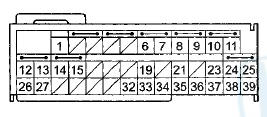
Wire side of female terminals
Is there continuity? YES
-Short to another wire in the SRS floor wire harness; replace the SRS floor wire harness, then clear the DTC.
NO
-Faulty SRS unit; replace the SRS unit (see page 24-228).
DTC 21-3x ("x" can be 0 thru 9 or A thru F):
Short to Another Wire or Decreased Resistance in the Driver's Seat Belt Tensioner
Special Tools Required
• SRS Inflator Simulator 07SAZ-TB4011A
• SRS Simulator Lead K 070AZ-SNAA200
• SRS Short Canceller 070AZ-SAA0100
NOTE: • Before doing this troubleshooting procedure, review SRS Precautions and Procedures (see page 24-25), General Troubleshooting Information (see page 24-36), and Battery Terminal Disconnection and Reconnection (see page 22-91).
• 2-door: Before replacing the SRS unit, check the SRS unit software version with the HDS. If the software version is not the latest, update the SRS unit software (see page 24-39), and retest.
1. Clear the DTC with the HDS (see page 24-38).
2. Turn the ignition switch to ON (II), then wait for 10 seconds.
3. Check for DTCs with the HDS (see page 24-37).
Is DTC 21-3x indicated? YES
-Go to step 4.
NO
-lntermittent failure, the system is OK at this time.
Go to Troubleshooting Intermittent Failures (see page 24-38). If another DTC is indicated, troubleshoot the DTC.
4. Turn the ignition switch to LOCK (0).
5.. Disconnect the negative cable from the battery, then wait at least 3 minutes.
6.4-door: Remove the left side B-pillar lower trim (see page 20-110).
7.2-door: Remove the rear left side trim panel (see page 20-132).
8. Disconnect the SRS floor wire harness 4P connector (A) from the driver's seat belt tensioner 4P connector.

9. Connect the SRS inflator simulator (2 Q connectors) and simulator lead K to the SRS floor wire harness.
10. Reconnect the negative cable to the battery.
11. Clear the DTC with the HDS (see page 24-38).
12. Check for DTCs with the HDS (see page 24-37).
Is DTC 21-3x indicated? YES
-Go to step 13.
NO
-Short to another wire in the driver's seat belt tensioner; replace the driver's seat belt, 4-door (see page 24-10), 2-door (see page 24-5), then clear the DTC.
13. Turn the ignition switch to LOCK (0).
14. Disconnect the negative cable from the battery, then wait at least 3 minutes.
15. Disconnect SRS unit connector B (39P) from the SRS unit (see step 11 on page 24-36).
16. Disconnect the simulator lead from the SRS floor wire harness.
17. Connect an SRS short canceller (070AZ-SAA0100) to SRS unit connector B (39P) terminals No. 12 and No. 13 (see page 24-32).
18. Measure the resistance between SRS unit connector
B (39P) terminals No. 12 and No. 13. There should be
an open circuit or at least 1 M .
.
SRS UNIT CONNECTOR B (39P)

Wire side of female terminals
Is the resistance as specified? YES
-Faulty SRS unit or poor connection at SRS unit connector B (39P) and the SRS unit. Check the connection; ifthe connection is OK, replace the SRS unit (see page 24-228).
NO
-Short to another wire in the SRS floor wire harness; replace the SRS floor wire harness, then clear the DTC.
DTC 21-8x ("x" can be 0 thru 9 or A thru F):
Short to Power In the Driver's Seat Belt Tensioner
Special Tools Required
• SRS Inflator Simulator 07SAZ-TB4011A
• SRS Simulator Lead K 070AZ-SNAA200
NOTE: • Before doing this troubleshooting procedure, review SRS Precautions and Procedures (see page 24-25), General Troubleshooting Information (see page 24-36), and Battery Terminal Disconnection and Reconnection (see page 22-91).
• 2-door: Before replacing the SRS unit, check the SRS unit software version with the HDS. If the software version is not the latest, update the SRS unit software (see page 24-39), and retest.
1. Clear the DTC with the HDS (see page 24-38).
2. Turn the ignition switch to ON (II), then wait for 10 seconds.
3. Check for DTCs with the HDS (see page 24-37).
Is DTC 21-8x Indicated? YES
-Go to step 4.
NO
-lntermittent failure, the system is OK at this time.
Go to Troubleshooting Intermittent Failures (see page 24-38). If another DTC is indicated, troubleshoot the DTC.
4. Turn the ignition switch to LOCK (0).
5. Disconnect the negative cable from the battery, then wait at least 3 minutes.
6.4-door: Remove the left side B-pillar lower trim (see page 20-110).
7.2-door: Remove the rear left side trim panel (see page 20-132).
8. Disconnect the SRS floor wire harness 4P connector (A) from the driver's seat belt tensioner 4P connector.
9. Connect the SRS inflator simulator (2 O connectors) and simulator lead K to the SRS floor wire harness.
10. Reconnect the negative cable to the battery.
11. Clear the DTC with the HDS (see page 24-38).
12. Check for DTCs with the HDS (see page 24-37).
Is DTC 21-8x indicated? YES
-Go to step 13.
NO-
Short to power in the driver's seat belt tensioner; replace the driver's seat belt, 4-door (see page 24-10), 2-door (see page 24-5), then clear the DTC.
13. Turn the ignition switch to LOCK (0).
14. Disconnect the negative cable from the battery, then wait at least 3 minutes.
15. Disconnect SRS unit connector B (39P) from the SRS unit (see step 11 on page 24-36).
16. Disconnect the simulator lead from the SRS floor wire harness.
17. Reconnect the negative cable to the battery.
18. Turn the ignition switch to ON (II).
19. Measure the voltage between body ground and SRS unit connector B (39P) terminals No. 12 and No. 13, individually. There should be less than 0.2 V.
SRS UNIT CONECTOR R ( 39P)
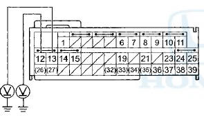
Wire side of female terminals
Is the voltage as specified? YES
-Faulty SRS unit or poor connection at SRS unit connector B (39P) and the SRS unit. Check the connection; ifthe connection is OK, replace the SRS unit (see page 24-228).
NO
-Short to power in the SRS floor wire harness; replace the SRS floor wire harness, then clear the DTC.
DTC 21-9x ("x" can be 0 thru 9 or A thru F):
Short to Ground in the Driver's Seat Belt Tensioner
Special Tools Required
• SRS Inflator Simulator 07SAZ-TB4011A
•SRS Simulator Lead K 070AZ-SNAA200
NOTE: • Before doing this troubleshooting procedure, review SRS Precautions and Procedures (see page 24-25), General Troubleshooting Information (see page 24-36), and Battery Terminal Disconnection and Reconnection (see page 22-91).
• 2-door: Before replacing the SRS unit, check the SRS unit software version with the HDS. If the software version is not the latest, update the SRS unit software (see page 24-39), and retest.
1. Clear the DTC with the HDS (see page 24-38).
2. Turn the ignition switch to ON (II), then wait for 10 seconds.
3. Check for DTCs with the HDS (see page 24-37).
Is DTC 21-9x indicated? YES
-Go to step 4.
NO
-lntermittent failure, the system is OK at this time.
Go to Troubleshooting Intermittent Failures (see page 24-38). If another DTC is indicated, troubleshoot the DTC.
4. Turn the ignition switch to LOCK (0).
5. Disconnect the negative cable from the battery, thenwait at least 3 minutes.
6.4-door: Remove the left side B-pillar lower trim (see page 20-110).
7.2-door: Remove the rear left side trim panel (see page 20-132).
8. Disconnect the SRS floor wire harness 4P connector (A) from the driver's seat belt tensioner 4P connector.

9. Connect the SRS inflator simulator (2 0 connectors) and simulator lead K to the SRS floor wire harness.
10. Reconnect the negative cable to the battery.
11. Clear the DTC with the HDS (see page 24-38).
12. Check for DTCs with the HDS (see page 24-37).
Is DTC 21-9x indicated? YES
-Go to step 13.
NO
-Short to ground in the driver's seat belt tensioner; replace the driver's seat belt, 4-door (see page 24-10), 2-door (see page 24-5), then clear the DTC.
13. Turn the ignition switch to LOCK (0).
14. Disconnect the negative cable from the battery, then wait at least 3 minutes.
15. Disconnect SRS unit connector B (39P) from the SRS unit (see step 11 on page 24-36).
16. Disconnect the simulator lead from the SRS floor wire harness.
17. Measure the resistance between body ground and
SRS unit connector B (39P) terminals No. 12 and
No. 13, individually. There should be an open circuit
or at least 1 M .
.
SRS UNIT CONNECTOR B (39P)
Wire side of female terminals
Is the resistance as specified? YES
-Faulty SRS unit or poor connection at SRS unit connector B (39P) and the SRS unit. Check the connection; if the connection is OK, replace the SRS unit (see page 24-228).
NO
-Short to ground in the SRS floor wire harness; replace the SRS floor wire harness, then clear the DTC.
DTC 22-1x ("x" can be 0.2 thru 9 or A thru F):
Open in the Front Passenger's Seat Belt Tensioner
Special Tools Required
• SRS Inflator Simulator 07SAZ-TB4011A
•SRS Simulator Lead K 070AZ-SNAA200
• SRS Short Canceller 070AZ-SAA0100
NOTE: В© Before doing this troubleshooting procedure, review SRS Precautions and Procedures (see page 24-25), General Troubleshooting Information (see page 24-36), and Battery Terminal Disconnection and Reconnection (see page 22-91).
• 2-door: Before replacing the SRS unit, check the SRS unit software version with the HDS. If the software version is not the latest, update the SRS unit software (see page 24-39), and retest.
1. Clear the DTC with the HDS (see page 24-38).
2. Turn the ignition switch to ON (II), then wait for 10 seconds.
3. Check for DTCs with the HDS (see page 24-37).
Is DTC 22-1 x Indicated? YES
-Go to step 4.
NO-
lntermittent failure, the system is OK at this time.
Go to Troubleshooting Intermittent Failures (see page 24-38). If another DTC is indicated, troubleshoot the DTC.
4 Turn the ignition switch to LOCK (0).
5. Disconnect the negative cable from the battery, then wait at least 3 minutes.
6.4-door: Remove the right side B-pillar lower trim (see page 20-110).
7.2-door: Remove the rear right side trim panel (see page 20-132).
8. Disconnect the SRS floor wire harness 4P connector (A) from the front passenger's seat belt tensioner 4P connector.
9. Connect the SRS inflator simulator (2 O connectors) and simulator lead K to the SRS floor wire harness.
10. Reconnect the negative cable to the battery.
11. Clear the DTC with the HDS (see page 24-38).
12. Check for DTCs with the HDS (see page 24-37).
Is DTC 22-1 x indicated? YES
-Go to step 13.
NO
-Open in the front passenger's seat belt tensioner; replace the front passenger's seat belt, 4-door (see page 24-10), 2-door (see page 24-5), then clear the DTC.
13. Turn the ignition switch to LOCK (0).
14 Disconnect the negative cable from the battery, then wait at least 3 minutes.
15. Disconnect SRS unit connector B (39P) from the SRS unit (see step 11 on page 24-36).
16. Connect an SRS short canceller (070AZ-SAA0100) to SRS unit connector B (39P) terminals No. 14 and No. 15 (see page 24-32).
17. Measure the resistance between SRS unit connector
B (39P) terminals No. 14 and No. 15. There should be
2.0-3.0  .
.
SRS UNIT CONNECTOR B (39P)
Wire side of female terminals
Is the resistance as specified? YES
-Faulty SRS unit or poor connection at SRS unit connector B (39P) and the SRS unit. Check the connection; ifthe connection is OK, replace the SRS unit (see page 24-228).
NO
-Open in the SRS floor wire harness; replace the SRS floor wire harness, then clear the DTC.
DTC 22-11:
Short to Another Wire in the Front Passenger's Seat Belt Tensioner (4-door)
NOTE: Before doing this troubleshooting procedure, review SRS Precautions and Procedures (see page 24-25), General Troubleshooting Information (see page 24-36), and Battery Terminal Disconnection and Reconnection (see page 22-91).
1. Clear the DTC with the HDS (see page 24-38).
2. Turn the ignition switch to ON (II), then wait for 10 seconds.
3. Check for DTCs with the HDS (see page 24-37).
Is DTC 22-11 indicated? YES
-Go to step 4.
NO
-lntermittent failure, the system is OK at this time.
Go to Troubleshooting Intermittent Failures (see page 24-38). If another DTC is indicated, troubleshoot the DTC.
4. Check for DTCs with the HDS (see page 24-37).
Is DTC 21-11, 31-11, 32-11, 33-11, or 34-11 indicated with DTC 22-11? YES
-Go to step 5.
NO
-Short to another wire in the SRS floor wire harness; replace the SRS floor wire harness, then clear the DTC.
5. Turn the ignition switch to LOCK (0).
6. Disconnect the negative cable from the battery, then wait at least 3 minutes.
7. Disconnect SRS unit connector B (39P) from the SRS unit (see step 11 on page 24-36).
8. Check for continuity between the terminals of SRS unit connector B (39P) according to the table. There should be no continuity.
SRS UNIT CONNECTOR B (39P)
Wire side of female terminals
Is there continuity? YES-
Short to anoth
 Circuit Diagram
4-Door
4-Door
2-Door
2-Door
...
 Symptom Troubleshooting
SRS indicator does not come on
NOTE: 2-door: Before replacing t h e SRS u n i t , check the
SRS u n i t software v e r s i o n w i t h t h e HDS. I f t h e software
v e r s i o n is not t h e lates ...
See also:
How Your Front Airbags Work
If you ever have a moderate to
severe frontal collision, sensors will
detect the vehicle’s rapid
deceleration.
If the rate of deceleration is high
enough, the control unit will inflate
...
Circuit Diagram
M/T model
A/T modeS
...
General Troubleshooting
Information
Lever-Locked Connector
Disconnecting
To disconnect the connector, pull the lever (A) while
pushing the lock tab (B) down, then pull the connector
(C).
Connecting
To connect the connector, push ...