 Honda Accord: DTC Troubleshooting
DTC B1775:
Microphone input/Output Short to Power/Open
NOTE: If you are troubleshooting multiple DTCs, be sure to follow the instructions in B-CAN system diagnosis test mode A (see page 22-134).
1. Connect the HDS to the DLC.
2. Clear the DTCs with the HDS.
3. Turn the ignition switch to LOCK (0) and then back to ON (II).
4. Check for DTCs with the HDS.
Is DTC B1775 Indicated? YES-
Go to step 5.
NO
-lntermittent failure, the system is OK at this time.
5. Turn the ignition switch to LOCK (0).
6. Disconnect the front HFL-ANC microphone 7P connector.
7. Disconnect the HandsFreeLink control unit 28P connector.
8. Turn the ignition switch to ON (II).
9. Measure the voltage between HandsFreeLink control unit 28P connector terminal No. 13 and body ground.
HANDSFREELINK CONTROL UNIT 28P CONNECTOR
Wire side of female terminals
Is there voltage? YES
-There is a short to power in the wire the HandsFreeLink control unit and the front HFL-ANC microphone. Replace the affected shielded harness.
NO
-Goto step 10.
10. Turn the ignition switch to LOCK (0).
1 1 . Check for continuity between HandsFreeLink control unit 28P connectorterminal No. 13 and front HFL-ANC microphone 7P connector terminal No. 3.
HANDSFREELINK CONTROL UNIT 28P CONNECTOR
Wire side of female terminals
FRONT HFL-ANC MICROPHONE 7P CONNECTOR
Wire side of female terminals
Is there continuity? YES
-Substitute a known-good HandsFreeLink control unit (see page 23-281), then recheck. If the symptom goes away, replace the original HandsFreeLink control unit. If the symptom still present, replace the HFL microphone (see page 23-280).
NO
-There is an open in the wire between the HandsFreeLink control unit and the front HFL-ANC microphone. Replace the affected shielded harness.
DTC B177S:
Microphone Input/Output Short to Ground/Open
NOTE; If you are troubleshooting multiple DTCs, be sure to follow the instructions in B-CAN system diagnosis test mode A (see page 22-134).
1. Connect the HDS to the DLC.
2. Clear the DTCs with the HDS.
3. Turn the ignition switch to LOCK (0) and then back to ON (II).
4. Check for DTCs with the HDS.
Is DTC B1776 indicated? YES
-Go to step 5.
NO
-lntermittent failure, the system is OK at this time.B 5. Turn the ignition switch to LOCK (0).
6. Disconnect the front HFL-ANC microphone 7P connector.
7 Disconnect the HandsFreeLink control unit 28P connector.
8. Check for continuity between body ground and the HandsFreeLink control unit 28P connector terminals No. 13 and No. 14 individually, then between terminals No. 12 and No. 13.
HANDSFREELINK CONTROL UNIT 28P CONNECTOR
Wire side of female terminals
Is there continuity? YES
-There is a short in the wire(s) between the HandsFreeLink control unit and the front HFL-ANC microphone. Replace the affected shielded harness.
NO
-Go to step 9.
9. Check for continuity between the terminals shown of the HandsFreeLink control unit 28P connector and the front HFL-ANC microphone 7P connector.
HANDSFREELINK CONTROL UNIT 28P CONNECTOR
Wire side of female terminals
FRONT HFL-ANC MICROPHONE 7P CONNECTOR
Wire side of female terminals
Is there continuity? YES
-Go to step 10.
NO
-There is an open in the wire(s) between the HandsFreeLink control unit and the front HFL-ANC microphone. Replace the affected shielded harness.
10. Disconnect navigation unit connector C (16P).
11. Check for continuity between body ground and HandsFreeLink control unit 28P connector terminals No. 27 and No. 28 individually.
HANDSFREELINK CONTROL UNIT 28P CONNECTOR
Wire side of female terminals
Is there continuity? YES
-There is a short to body ground in the wire(s) between the HandsFreeLink control unit and the navigation unit. Replace the affected shielded harness.
NO
-Go to step 12
12. Check for continuity between the terminals shown of the HandsFreeLink control unit 28P connector and navigation unit connector C (16P).
HANDSFREELINK CONTROL UNIT 28P CONNECTOR
Wire side of female terminals
NAVIGATION UNIT CONNECTOR C (16P)
Wire side of female terminals
Is there continuity? YES
-Substitute a known-good HandsFreeLink control unit (see page 23-281), then recheck. If the symptom goes away, replace the original HandsFreeLink control unit. If the symptom does not go away, replace the navigation unit (see page 23-238).
NO
-There is an open in the wire(s) between the HandsFreeLink control unit and the navigation unit. Replace the affected shielded harness.
DTC B1779:
HFL Switch or Voice Control Switch (HFL TALK/HFL BACK Buttons) Circuit Open/Short to power
NOTE: If you are troubleshooting multiple DTCs, be sure to follow the instructions in B-CAN system diagnosis test mode A (see page 22-134).
1. Connect the HDS to the DLC.
2. Clear the DTCs with the HDS.
3. Turn the ignition switch to LOCK (0), then start the vehicle, and turn the steering wheel back and forth several times. 4. Check for DTCs with the HDS.
Is DTC B1779 indicated? YES
-Go to step 5.
NO
-lntermittent failure, the system is OK at this time.
5. Turn the ignition switch to LOCK (0).
6. Do the HFL Switch Test (see page 23-279).
Is the switch OK? YES
-Go to step 7.
NO
-Replace the HFL-voice control switch (see page 17-7).
7 Disconnect HandsFreeLink control unit 28P connector.
8. Disconnect HFL-voice control switch SP connector.
9. Turn the ignition switch to ON (II).
10. Measure the voltage between HFL-voice control switch 5P connector terminal No, 3 and body ground.
HFL-VOICE CONTROL SWITCH SP CONNECTOR
Wire side of female terminals
Is them voltage? YES
-Repair a short to power in the BLU wire.
NO-
Go to step 11.
11. Turn the ignition switch to LOCK (0).
12. Check for continuity between HandsFreeLink control unit 28P connector terminal No. 2 and HFL-voice control switch 5P connector terminal No. 3.
HANDSFREELINK CONTROL UNIT 28P CONNECTOR
Wire side of female terminals
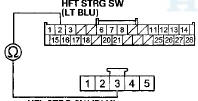
HFL STRG SW (BLU)
HFL-VOICE CONTROL SWITCH 5P CONNECTOR
Wire side of female terminals
Is there continuity? YES
-Go to step 13.
NO
-Repair an open in the BLU wire between the switch, the cable reel, and the HandsFreeLink control unit.
13. Turn the ignition switch to ON (II).
14. Measure the voltage between HandsFreeLink control unit 28P connector terminal No. 2 and body ground.
HANDSFREELINK CONTROL UNIT 28P CONNECTOR
Wire side of female terminals
Is there voltage? YES
-Repair a short to power in the wire between the HandsFreeLink control unit and the HFL-voice control s witch. N O
- G o to step 15.
15. Turn the ignition switch to LOCK (0).
16. Check for continuity between HFL-voice control switch 5P connector terminal No. 4 and body ground.
HFL-VOICE CONTROL SWITCH 5P CONNECTOR
Wire side of female terminals
Is there continuity? YES
-Replace the HandsFreeLink control unit (see page. 23-281 ) . NO
-Repair an open in the wire between the HFL-voice control switch, cable reel, and the audio unit.
DTC B1780:
HFL Switch (HFL TALK/HFL BACK Buttons) Circuit Short
NOTE: If you are troubleshooting multiple DTCs, be sure to follow the instructions in B-CAN system diagnosis test mode A (see page 22-134).
1. Connect the HDS to the DLC.
2. Clear the DTCs with the HDS.
3. Turn the ignition switch to LOCK (0), then start the vehicle, and turn the steering wheel back and forth several times.
4. Check for DTCs with the HDS.
Is DTC B1780 indicated? YES
-Go to step 5.
NO
-lntermittent failure, the system is OK at this t i m e .
5. Turn the ignition switch to LOCK (0).
6. Do the HFL Switch Test (see page 23-279).
Is the switch OK? YES
-Go to step 7.
NO
-Replace the cable reel subharness (see page 17-7).
7. Disconnect the HandsFreeLink control unit 28P connector.
8. Disconnect the HFL-voice control switch 5P connector.
9. Check for continuity between HandsFreeLink control unit 28P connector terminal No. 2 and body ground.
HANDSFREELINK CONTROL UNIT 28P CONNECTOR
Wire side of female terminals
Is there continuity? YES
-Repair a short in the wire.
NO
-Replace the HandsFreeLink control unit (see page 23-281 ) .
DTC B1792
: HandsFreeLink Control Unit Internal Error
1. Connect the HDS to the DLC.
2. Clear the DTCs with the HDS.
3. Turn the ignition switch to LOCK (0) and then back to ON (II).
4. Check for DTCs with the HDS.
Is DTC B1792 indicated? YES
-Replace the HandsFreeLink control unit (see page 23-281 ) . NO
-lntermittent failure, the system is OK at this time.
 Circuit Diagram
...
 Symptom Troubleshooting
The HFL digits do not go away from the
audio-HVAC subdisplay or the audio HVAC
display after pressing the HFL BACK button
1. Connect the HDS to the DLC (see page 23-252).
2. Clear the DTCs with ...
See also:
Transaxle
Priweline/Ajcle ...
Driver's Power Seat Motor Test
1. Remove the d r i v e r ' s seat (see page 20-194).
2. Remove t h e p o w e r seat adjustment switch knobs a nd
t h e recline cover f r om t h e seat.
• 4-door (see page 20-234)
• ...
Special Tools
Component Location Index
...