
 Honda Accord: Driveshaft Disassembly
Special'Tools Required
•Threaded Adapter, 26 x 1.5 mm 07XAC-001030A
-Slide Hammer 5/8M-18 UNF, commercially available
-Bearing Puller, commercially available
-Boot Band Pliers, commercially available
Inboard Joint Side
1. Remove the boot bands. Be careful not to damage the boot.
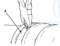
-If the boot band is a welded type (A), cut the boot band.
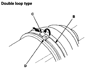
-If the boot band is a double loop type (B), lift up the band end (C), and push It into the clip (D).
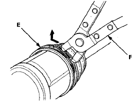
-If the boot band is a low profile type (E), pinch the boot band using commercially available boot band pliers (F).
Welded type
Low profile type
2. Make marks (A) on each roller (B) and the inboard joint (C) to identify the locations of the rollers to the grooves in the inboard joint.
NOTE: Do not engrave or scribe any marks on the rolling surface.
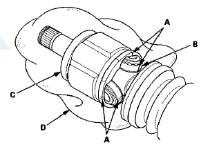
3. Remove the inboard joint on a clean shop towel (D).
Be careful not to drop the rollers when separating them from the inboard joint.
4 . Make marks (A) on the spider (B) that match the marks on the rollers, then remove the rollers.
NOTE: Do not engrave or scribe any marks on the rolling surface.
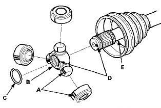
5. Remove the circlip (C).
6. Make marks (D) on the spider and the driveshaft (E) to identify the position of the spider on the shaft.
7. Remove the spider.
NOTE: If necessary, use a commercially available puller while being careful not to damage the spider.
8. Wrap the splines on the driveshaft with vinyl tape (A) to prevent damaging the inboard boot.
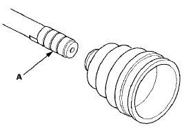
9. Remove the inboard boot. Be careful not to damage the boot.
10. Remove the vinyl tape.
Outboard Joint Side
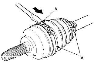
1 Remove the boot bands (A). Lift up the three tabs (B) using a screwdriver, then release the band. Be careful not to damage the boot.
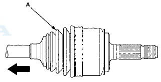
2. Slide the outboard boot (A) partially toward the inboard joint side. Be careful not to damage the boot.
3. Wipe off the grease to expose the driveshaft and the outboard joint inner race.
4. Make a mark (A) on the driveshaft (B) at the same level
as the outboard joint end (C).
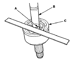
5. Securely clamp the driveshaft in a bench vise with a
shop towel wrapped around the driveshaft.
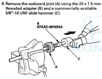
7. Remove the driveshaft from the bench vise.
8. Remove the stop ring from the driveshaft.
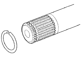
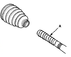
9. Wrap the splines on the driveshaft with vinyl tape (A)
to prevent damaging the outboard boot,

 Driveshaft Removal
Special Tools Required
-Ball Joint Thread Protector, 14 mm 07AAE-SJAA100
-Ball Joint Remover, 28 mm 07MAC-SL0A202
1. Raise and support the vehicle, (see page 1-13)
2. Remove the front wheels.
3 ...
 Dynamic Damper Replacement
1. Remove the Inboard joint (see page 16-7).
2. Remove the dynamic damper band (see step 1 on
page 16-7).
3. Remove the dynamic damper (A).
Left driveshaft
Right driveshaft
4. Install a ...
See also:
Component Location Index
'10 model
...
Shift Lock Release
This allows you to move the shift
lever out of Park if the normal
method of pushing on the brake
pedal and pressing the release
button does not work.
1. Set the parking brake.
2. Remove the ...
Clutch Interlock Switch T e s t
M/T model
1. Disconnect the clutch interlock switch connector (A).
2. Remove the clutch interlock switch (B).
3. Check for continuity between the terminals according
to the table.
- If the ...