 Honda Accord: Crankshaft Pulley Removal and Installation
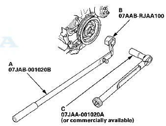
Special Tools Required
Handle, 6-25-660L 07JAB-001020B
Crankshaft Pulley Holder 07AAB-RJAA100
Socket, 19 mm 07JAA-001020A or equivalent
Removal
1 . Remove the front wheels.
2. Remove the splash shield (see step 25 on page 5-5).
3. Remove the drive belt (see page 4-30).
4. Hold the pulley with the handle, 6-25-660L (A) and the crankshaft pulley holder (B).
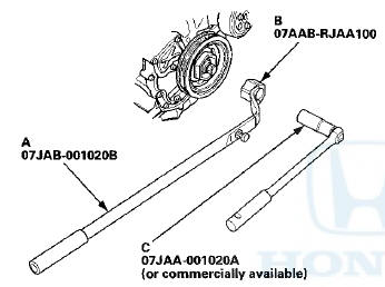
5. Remove the bolt with a socket, 19 mm (C) and a breaker bar, then remove the crankshaft pulley.
Installation
1. Clean the crankshaft pulley (A), the crankshaft (B), the bolt (C), and the washer (D). Lubricate with new engine oil as shown.

2. Install the crankshaft pulley, and holder the pulley with the handle (A) and the crankshaft pulley holder (B).
3. Torque the bolt to 49 N-m (5.0 kgf-m, 36 Ibf-ft) with a torque wrench and socket, 19 mm (C). Do not use an impact wrench. If the pulley bolt or crankshaft are new, torque the bolt to 177 N-m (18.0 kgf-m, 130 Ibf-ft), then remove the bolt and torque it to 49 N-m (5.0 kgf-m, 36 Ibf-ft).
4. Tighten the pulley bolt an additional 90 Р’В°.
5. Install the drive belt (see page 4-30).
6. Install the splash shield (see step 47 on page 5-20).
7. Install the front wheels.
 Valve Clearance Adjustment
Special Tools Required
. Locknut Wrench 07MAA-PR70120
. Adjuster 07MAA-PR70110
NOTE: Connect the Honda Diagnostic System (HDS) to
the data link connector (DLC) and monitor the engine
coolant temp ...
 Cam Chain Removal
NOTE: Keep the cam chain away from magnetic fields.
1. Remove the front wheels.
2. Remove the splash shield (see step 25 on page 5-5).
3. Remove the drive belt (see page 4-30).
4. Remove t ...
See also:
A/C Condenser Fan Circuit
Troubleshooting
NOTE:
• Do not use this troubleshooting procedure if the
radiator fan and/or the A/C compressor is inoperative.
Refer to the symptom troubleshooting index.
• Before doing symptom tro ...
Driver’s Seat Manual Height Adjustment
LX and EX models
The height of your driver’s seat is
adjustable. To raise the seat,
repeatedly pull up the lever on the
outside of the seat cushion. To lower
the seat, push the lever down ...
Valve Body
Valve Body and ATF Strainer
Installation
Exploded View
Torque Specifications:
6 x 1.0 mm: 12 N-m (1.2 kgf m, 8.7 Ibfft)
8 x 1.25 mm: 18 N-m (1.8 kgfm, 13 Ibfft)
NOTE: Refer to the Exploded Vie ...