 Honda Accord: Control Unit Input Test
NOTE: Before testing, troubleshoot the multiplex integrated control unit first, using B-CAN System Diagnosis Test Mode A (see page 22-134).
Driver's MICU
1. Turn the ignition switch to LOCK (0), and remove the driver's dashboard lower cover (see page 20-166).
2. Disconnect driver's under-dash fuse/relay box connectors D, Q, and R.
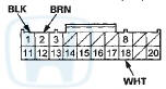
NOTE: All connector views are wire side of female terminals.
CONNECTOR D (16P)
CONNECTOR Q (20P)
CONNECTOR R (24P)
3. Inspect the connector and socket terminals to be sure they are all making good contact.
• If the terminals are bent, loose or corroded, repair them as necessary, and recheck the system.
• If the terminals are OK, go to step 4 .
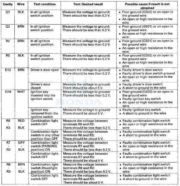
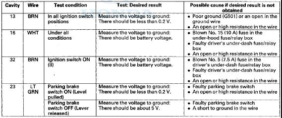
4. Reconnect the connectors, turn the Ignition switch to ON (II), and do these input tests at the following connectors.
• If any test indicates a problem, find and correct the cause, then recheck the system.
• If all the input tests prove OK, go to step 5.
Gauge Control Module
5. Turn the ignition switch to LOCK (0).
6. Remove the gauge control module (see page 22-351), and disconnect the 32P connector from it,
GAUGE CONTROL MODULE 32P CONNECTOR
Wire side of female terminals
7. Inspect the connector and socket terminals to be sure they are all making good contact • If the terminals are bent, loose or corroded, repair them as necessary, and recheck the system.
• If the terminals are OK, go to step 8.
8. Reconnect the connector to the gauge control module, turn the ignition switch to ON (II), and do these input tests at all following connector.
• If any test indicates a problem, find and correct the cause, then recheck the system.
• If the input tests prove OK, go to step 9.
9. Do the Gauge Control Module Self-diagnostic Function (see page 22-332), and check the beeper and the seat belt reminder indicator.
• If the beeper sounds and the seat belt reminder indicator flashes, go to step 10.
• If the beeper does not sound or the seat belt reminder indicator does not flash, replace the gauge control module (see page 22-351).
10. Substitute a known-good gauge control module, and recheck the system.
• If the symptom is gone, the gauge control module is faulty; replace it.
• If the symptom is still present, the driver's MICU is faulty; replace the driver's under-dash fuse/relay box.
- USA models (see page 22-86) - Canada models (see page 22-87)
 Circuit Diagram
...
 Moonroof
...
See also:
Glove Box
Open the glove box by pulling the
handle to the left. Close it with a firm
push. Lock or unlock the glove box
with the master key.
An open glove box can cause
serious injury to your passe ...
Playing a CD
Your audio system supports audio CDs, CD-Rs and CD-RWs in either MP3, WMA, or
AAC*1 format. With the CD loaded, press the CD button.
• How to Select a File from the Music Search List
(MP3/WMA ...
Inboard Joint Side
1. Wrap the splines with on the driveshaft vinyl tape (A)
to prevent damaging the inboard boot.
2. Install the inboard boot onto the driveshaft, then
remove the vinyl tape. Be careful not to dama ...