 Honda Accord: Control Unit Input Test
NOTE: Before testing, troubleshoot the multiplex integrated control unit first, using B-CAN System Diagnosis Test Mode A (see page 22-134),
Driver's MICU
1. Turn the ignition switch to LOCK (0), and remove the driver's dashboard lower cover (see page 20-166).
2. Disconnect driver's under-dash fuse/relay box connectors D, P, Q, and R.
NOTE: All connector views are shown from wire side of female terminals.
CONNECTOR D (16P)
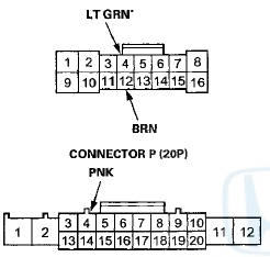
CONNECTOR Q (20P)
* : 4-door
3. Inspect the connector and socket terminals to be sure they are all making good contact.
• If the terminals are bent, loose or corroded, repair them as necessary and recheck the system.
• If the terminals look OK, go to step 4.
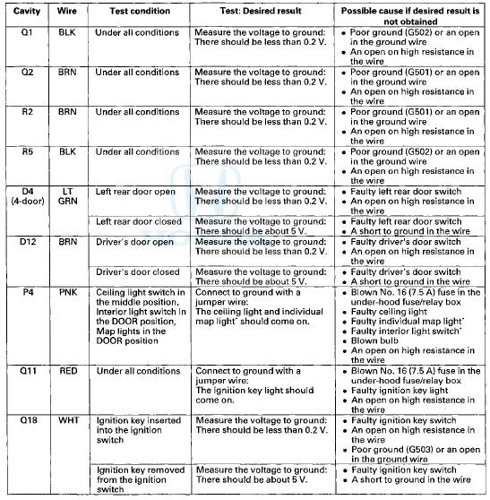
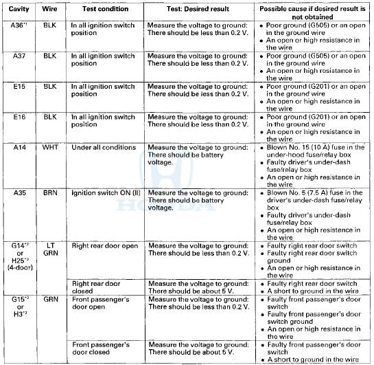
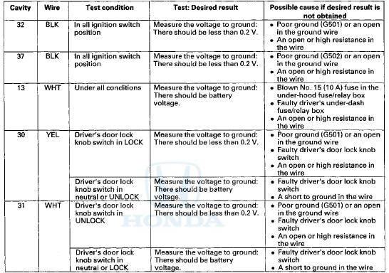
4. Reconnect the connectors to the driver's under-dash fuse/relay box, and do these input tests at the following connectors.
• If any test indicates a problem, find and correct the cause, then recheck the system.
• If all the input tests prove OK, go to step 5.
*: With moonroof
Passenger's MICU
5. Turn the ignition switch to LOCK (0), and remove the passenger's kick panel
• 2-door (see page 20-105)
• 4-door (see page 20-107)
6. Disconnect passenger's under-dash fuse/relay box connectors A, E, and G# 1(or H*2).
*1:LX, LX PZEV, LX-P, LX-P PZEV
*2: Except LX, LX PZEV, LX-P, LX-P PZEV
NOTE: All connector views are wire side of female terminals.
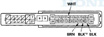
CONNECTOR A (38P)
CONNECTOR E (18P)
*1:4-door
*2: '08-09 models
CONNECTOR G (16P) (LX, LX PZEV, LX-P. LX-P PZEV
CONNECTOR H (38P) (Except LX, LX PZEV, LX-P, LX-P
7. Inspect the connector and socket terminals to be sure they are all making good contact.
• If the terminals are bent, loose or corroded, repair them as necessary and recheck the system.
• If the terminals look OK, go to step 8.
8. R e c o n n e c t t h e c o n n e c t o r s to t h e p a s s e n g e r ' s u n d e r - d a s h f u s e / r e l a y b o x , a n d d o t h e s e input tests at t h e f o l l o w i ng c o n n e c t o r s .
• If a n y t e s t i n d i c a t e s a p r o b l e m , f i n d and c o r r e c t t h e c a u s e , t h e n r e c h e c k t h e s y s t e m .
• If a l l t h e i n p u t t e s t s p r o v e OK, g o t o s t e p 9.
*1: '08-09 models
*2: LX, LX PZEV, LX-P, LX-P PZEV
*3: Except LX, LX PZEV, LX-P, LX-P PZEV
Door Multiplex Control Unit
9. Turn the ignition switch to LOCK (0), and remove the power window master switch (see page 22-305).
10. Disconnect the 37P connector from the door multiplex control unit.
DOOR MULTIPLEX CONTROL UNIT 37P CONNECTOR
Wire side of female terminals
11. Inspect the connector and socket terminals to be sure they are all making good contact.
• If the terminals are bent, loose or corroded, repair them as necessary and recheck the system.
• If the terminals look OK, go to step 12.
12. Reconnect the 37P connector to the door multiplex control unit and do these input tests at the following connector.
• If any test indicates a problem, find and correct the cause, then recheck the system.
• If all the input tests prove OK, go to step 13.
13. If multiple failures are found on more than one control unit, replace the driver's under-dash fuse/relay box (includes the driver's MICU).
• USA models (see page 22-86)
• Canada models (see page 22-87)
If input failures are related to a particular control unit, replace the control unit.
 Circuit Diagram
...
 Ignition Key Switch Test
1. Remove the steering column upper and lower covers
(see page 20-181).
2. Disconnect the 6P connector (A).
3. Check for continuity between terminals No. 1 and No.
2.
• There should ...
See also:
XM® Radio Service*
• Subscribing to XM® Radio
1. You need your radio ID ready before registering for subscription. To see
the ID in
the display: Turn the selector knob or the interface dial until 0 appears.
2. ...
Ignition Switch and Power ModeComparison
...
Headlight Aiming
The headlights were properly aimed
when your vehicle was new. If you
regularly carry heavy items in the
trunk or pull a trailer, readjustment
may be required. Adjustments
should be done by y ...