 Honda Accord: Column Cover Removal/Installation
NOTE: - Put on gloves to protect your hands.
- Take care not to scratch or damage the column covers.
- Do not pry the cover surface with any tools.
1. Adjust the steering column to the full tilt down position, and to the full telescopic out position .
2. Remove the column blind cover by detaching the clips from the upper column cover (see step 2 on page 20-165).
3. Turn the steering wheel to the left, and release the left tab (A) of the upper column cover (B) while pushing on the lower column cover (C) from the front side.

Carefully release the tabs, and note the hooks (D) may break when the upper column cover is pulled up too hard.
4. Turn the steering wheel to the right, and release the right tab of the upper column cover the same way as in step 3.
5. Insert a suitable sized screwdriver or equivalent tool (A) along the guide rib (B) into the lever hole (C) in the lower column cover (D).
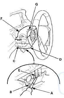
6. Release the hook (E) locating on the left side of the upper column cover (F). The right side hook (G) of the upper column cover can not be released from the inside.
7. Remove the upper column cover (A) by lightly pulling it up while releasing the right side hook (B, C) of the cover.
8. Remove the screws (A, B), then remove the lower column cover (C).
9. Install the upper and the lower column covers in the reverse order of removal, and push the hooks into place securely.
 Passenger's Middle Pad
Removal/Installation
Passenger's Middle Pad
Removal/Installation
Special Tools Required
KTC Trim Tool Set SOJATP2014*
*Available through the Honda Tool and
Equipment
Program; call 888-424-6857
SRS components are located in this area. Review the
SRS component ...
 Dashboard/Steering Hanger Beam
Removal/Installation
Dashboard/Steering Hanger Beam
Removal/Installation
Special Tools Required
KTC Trim Tool Set SOJATP2014*
*Available through the Honda Tool and Equipment
Program; call 888-424-6857
SRS components are located in this area. Review the
SRS component l ...
See also:
System Description
VSA Modulator-Control Unit Inputs and Outputs for 36P Connector (Connector
Disconnected
Wire side of female terminals.
System Outline
This system i s composed of the VSA modulator-control u ...
Fuel Pulsation Damper Replacement
PZEV model
1. Relieve the fuel pressure (see page 11-306).
2. Remove the engine cover.
3. Place a wrench (A) on the fuel rail (B).
4. Place a wrench (C) on the fuel pulsation damper (D),
an ...