 Honda Accord: Circuit Diagram
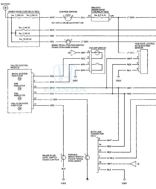
DRIVER'S UNDER-DASH FUSE/RELAY BOX CONNECTOR P (20P)
BRAKE PEDAL POSITION SWITCH 4P CONNECTOR

GAUGE CONTROL MODULE 32P CONNECTOR

VSA OFF SWITCH BP CONNECTOR

YAW RATE-LATERAL ACCELERATION SENSOR" 5P CONNECTOR

BRAKE FLUID 'LEVEL SWITCH 2P CONNECTOR'

PARKING BRAKE SWITCH 1P CONNECTOR

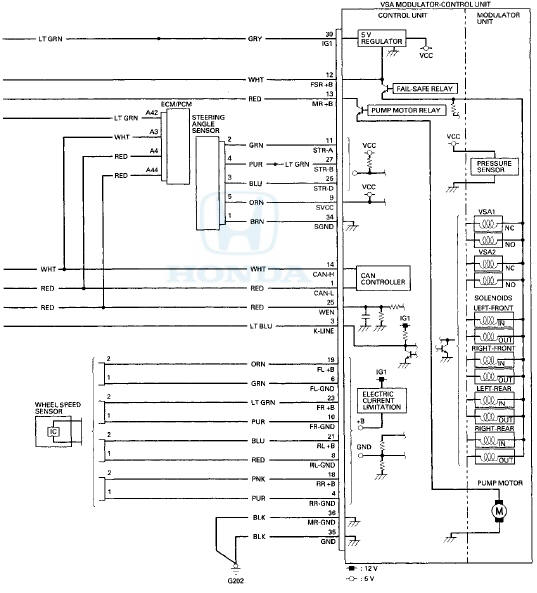
STEERING ANGLE SENSOR 5P CONNECTOR

WHEEL SPEED SENSOR 2P CONNECTOR

VSA MODULATOR-CONTROL UNIT 36P CONNECTOR
Wire side of female terminals
ECM/PCM CONNECTOR A (49P)
DATA LINK CONNECTOR (DLC)
Terminal side of female terminals
 System Description
VSA Modulator-Control Unit Inputs and Outputs for 36P Connector (Connector
Disconnected
Wire side of female terminals.
System Outline
This system i s composed of the VSA modulator-control u ...
 DTC Troubleshooting
DTC 11-13: Right-front Wheel Speed Sensor
Circuit Malfunction
DTC 13-13; Left-front Wheel Speed Sensor
Circuit Malfunction
DTC 15-13: Right-rear Wheel Speed Sensor
Circuit Malfunction
DTC 17-13: ...
See also:
Overheating
How to Handle Overheating
Overheating symptoms are as follows:
• The temperature gauge needle is at the
mark or the engine suddenly loses
power.
• Steam or spray comes out of the engine co ...
How to Use HFL
The ignition switch must be in the ACCESSORY (I) or ON (II) position.
To use HFL, you need to pair your
Bluetooth-compatible cell phone to
the system. ...
Oil Seal Replacement
Special Tools Required
- Driver Handle, 15 x 135L 07749-0010000
- Oil Seal Driver Attachment 07NAD-P20A100
1. Remove the oil seal (A) from the transmission
housing (B).
...