 Honda Accord: Cam Chain Installation
Special Tools Required
Camshaft Lock Pin Set 07AAB-RWCA120
NOTE: - Keep the cam chain away from magnetic fields.
- Before doing this procedure, check that the variable valve timing control (VTC) actuator is locked by turning the VTC actuator counterclockwise. If not locked, turn the VTC actuator clockwise until it stops, then recheck it. If it is still not locked, replace the VTC actuator.
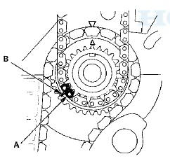
1. Set the crankshaft to top dead center (TDC). Align the TDC mark (A) on the crankshaft sprocket with the pointer (B) on the engine block.
2. Set the camshafts to TDC. The punch mark (A) on the VTC actuator and the punch mark (B) on the exhaust camshaft sprocket should be at the top. Align the TDC marks (C) on the VTC actuator and the exhaust camshaft sprocket.
3. To hold the intake camshaft, insert a camshaft lock pin set (P/N 07AAB-RWCA120) (A) into the maintenance hole in camshaft position (CMP) pulse plate A (B) and through the No. 5 rocker shaft holder (C).
4. To hold the exhaust camshaft, insert a camshaft lock pin (A) into the maintenance hole in CMP pulse plate B (D) and through the No. 5 rocker shaft holder (C).
5. Install the cam chain on the crankshaft sprocket with the colored link plate (A) aligned with the mark (B) on the crankshaft sprocket.
6. Install the cam chain on the VTC actuator and the exhaust camshaft sprocket with the punch marks (A) aligned with the center of the two colored link plates (B).
7. Install cam chain guide A and the tensioner arm (B).
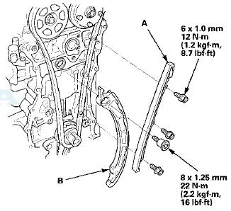
8. Install cam chain guide B.
9. Compress the auto-tensioner when replacing the cam chain. Remove the pin (P/N 1451 t-PNA-003).(A) from the auto-tensioner that was installed during removal.
Turn the plate f B) counterclockwise, to release the lock, then press the rod (C), and set the first cam (D) to the first edge of the rack (E). Insert the 1.2 mm (0.05 in) diameter pin or lock pin into the holes (F).
NOTE: If the chain tensioner is not set up as described, the tensioner will become damaged.
10. Install the auto-tensioner.
11 Remove the pin or lock pin from the auto-tensioner.
12. Remove the camshaft lock pin set.
13. Check the chain case oil seal for damage. If the oil seal is damaged, replace the chain case oil seal {see page 6-71).
14. Remove the old liquid gasket from the chain case mating surfaces, the bolts, and the bolt holes.
15. Clean and dry the chain case mating surfaces.
16. Apply liquid gasket, P/N 08717-0004, 08718-0003, or 08718-0009 to the engine block mating surface of the chain case, and to the inside edge of the threaded bolt holes, install the component within 5 minutes of applying the liquid gasket.
NOTE: - Apply a 3 mm (0.12 in) diameter bead of liquid gasket along the broken line (A).
- If too much time has passed after applying the liquid gasket, remove the old liquid gasket and residue, then reapply new liquid gasket.
17. Apply liquid gasket to the engine block upper surface contact areas (B) on the chain case and lower block upper surface contact areas (C) on the chain case.
18. Apply liquid gasket, P/N 08717-0004,08718-0003, or 08718-0009 to the oil pan mating surface of the chain case, and to the inside edge of the threaded bolt holes. Install the component within 5 minutes of applying the liquid gasket.
NOTE: - Apply a 3 mm (0.12 in) diameter bead of liquid gasket along the broken line (A).
- If too much time has passed after applying the liquid gasket, remove the old liquid gasket and residue, then reapply new liquid gasket.
19. Install the spacer (A), then install the new O-ring (B) on the chain case. Set the edge of the chain case (C) to the edge of the oil pan {D), then install the chain case on the engine block (E). Wipe off the excess liquid gasket on the oil pan and chain case mating surface.
NOTE: - When installing the chain case, do not slide the bottom surface onto the oil pan mounting surface.
- Wait at least 30 minutes before filling the engine with oil.
- Do not run the engine for at least 3 hours after installing the chain case.
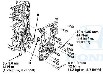
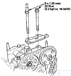
20. Install the side engine mount bracket, then tighten the side engine mount bracket mounting bolts.
21. Tighten the new side engine mount bracket mounting bolts in the numbered sequence shown.
22. Install the ground cable.
23. Remove the jack and the wood block.
24. Install the crankshaft pulley (see page 6-61).
25. Install the VTC oil control solenoid valve (see page 11-273).
26. Connect the VTC oil control solenoid valve connector (A) and install the harness clamp (B).
27. Install the cylinder head cover (see page 6-74).
28. Install the drive belt (see page 4-30).
29. Install the splash shield (see step 47 on page 5-20).
30. Install the front wheels.
31. Do the crankshaft position (CKP) pattern clear/CKP pattern learn procedure (see page 11-5).
 Cam Chain Removal
NOTE: Keep the cam chain away from magnetic fields.
1. Remove the front wheels.
2. Remove the splash shield (see step 25 on page 5-5).
3. Remove the drive belt (see page 4-30).
4. Remove t ...
 Cam Chain Auto-tensioner Removal
and installation
Cam Chain Auto-tensioner Removal
and installation
Removal
1.Remove the chain case cover
2. Turn the crankshaft counterclockwise to compress the
auto-tensioner.
3. Align the holes on the lock (A) and the auto-tensioner
(B), then insert a 1.2 ...
See also:
Audio System Basic Operation
To use the audio system function, the power mode must be in ACCESSORY or ON.
Use the interface dial or MENU button to
access some audio functions.
Press to switch between the
normal and
ext ...
Alternator Control Circuit
Troubleshooting
NOTE: Do this troubleshooting if, in step 5 of the
alternator and regulator circuit troubleshooting (see
page 4-27), the battery voltage is less than 13.5 V.
* 1. Connect the Honda Diagnostic Sys ...
System Description
General Description
The automatic transmission is a transverse-mounted three-shaft design,
implemeting an electronically controlled
hydraulic circuit that provides five forward speeds and one in r ...