 Honda Accord: Brake Pedal and Brake Pedal Position Switch
Adjustment
Honda Accord: Brake Pedal and Brake Pedal Position Switch
Adjustment
Pedal Height
1. Turn t h e brake p e d a l p o s i t i o n switch 45В° counterclockwise, and pull it back until it is no longer touching the brake pedal.
2. Remove the footrest (see step 4 on page 20-151), then remove the steering joint cover (see page 17-10).
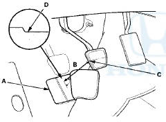
3. Pull back the carpet, and find the cutout (A) in the insulation. Measure the pedal height (B) from left side middle of the brake pedal pad (C) to the floor (D) without the insulation as shown.
Standard pedal height (with carpet removed):
M/T: 156 mm (6.1 in)
A/T: 155 mm (6.1 in)
M/T
4. Loosen the pushrod locknut (A), and screw the pushrod (B) in or out with pliers until the standard pedal height from the floor is reached. After adjustment, tighten the locknut firmly. Do not adjust the pedal height with the pushrod pressed.
Brake Pedal Position Switch Adjustment
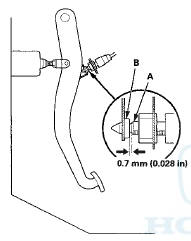
5. Lift up on the brake pedal by hand. Push in the brake pedal position switch until its plunger is fully pressed (threaded end (A) touching the pad (B) on the pedal arm). Turn the switch 45 В° clockwise to lock it. The gap between the brake pedal position switch and the pad is automatically adjusted to 0.7 mm (0.028 in) by locking the switch. Make sure the brake lights go off when the pedal is released.
6. Install all removed parts in the reverse order of removal.
7. Check the brake pedal free play.
Pedal Free Play
1. With the ignition switch in LOCK (0), inspect the free play (A) at the pedal pad (B) by pushing the brake pedal by hand. If the brake pedal free play is out of specification, adjust the brake pedal position switch (C). If the brake pedal free play is insufficient, it may result in brake drag.
Free play: 1 —5 mm (0.04—0.20 in)
 Symptom Troubleshooting
Rapid brake pad wear, vehicle vibration
(after a long drive), or high, hard brake pedal
NOTE: Make sure that the caliper pins are installed
correctly. Upper caliper pin B and lower caliper pin A ar ...
 Parking Brake Inspection and Adjustment
Inspection
1. Pull the parking brake lever (A) with 196 N
(20 kgf, 44 Ibf) of force to fully apply the parking brake.
The parking brake lever should be locked within the
specified number of clic ...
See also:
Multi-View Rear Camera
About Your Multi-View Rear Camera
The audio/information screen can display your vehicle’s rear view. The
display
automatically changes to the rear view when the shift lever is moved to (R.
T ...
Trim Removal/Installation - Rear Shelf Area
Special Tools Required
KTC Trim Tool Set SOJATP2014*
*Available through the Honda Tool and
Equipment
Program; call 888-424-6857
Rear Shelf
SRS components are located in this area. Review the
S ...
To Play the FM/AM Radio
The ignition switch must be in the
ACCESSORY (I) or the ON (II)
position. Press the AUDIO button to
view the audio control display. Turn
the system on by pressing the
power/volume knob or ...