 Honda Accord: Ball Joint Boot Inspection / Replacemen
Special Tools Required
- Clip Guide, 45 mm 070AG-SJA0300
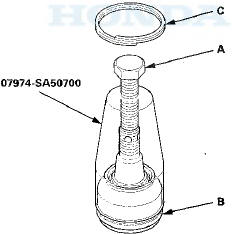
-Clip Guide, 41 mm 07974-SA50700
1. Check the ball joint boot for weakness, damage, cracks, and grease leaks.
NOTE: - If the ball joint boot is damaged with grease leaks, replace the appropriate part as an assembly.
- If the ball joint boot is soft and cracked without grease leaks, go to step 2. Replace the appropriate ball joint boot.
2. Disconnect the appropriate ball joint connection, and remove the component including the ball joint:
- The front knuckle (see page 18-14)
- The front upper arm (see page 18-19)
- The rear upper arm (see page 18-43)
3. Remove the boot clip and the boot.
4. Pack the interior and lip (A) of a new boot with grease.
Keep the grease off of the boot-to-housing mating surfaces (B).
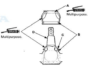
5. Pack fresh grease into the base (C). Do not let dirt or other foreign materials get into the boot.
6. Install the boot on the ball joint, then squeeze it gently to force out any air, then wipe the grease off the tapered portion of the ball joint pin (D).
7. The front knuckle ball joint or the rear upper arm ball joint: Adjust the depth by turning the clip guide until its base is just above the groove around (A) the bottom of the boot. Then slide the clip (B) over the clip guide and into position on the boot.
8. The front upper arm ball joint: Adjust the clip guide with the adjusting bolt (A) until its base is just above the groove around (B) the bottom of the boot. Then slide the clip (C) over the clip guide and into position on the boot.
9. After installing a boot wipe any grease off the exposed portion of the ball joint pin.
10. Install all of the removed parts.
 Ball Joint Removal
Special Tools Required
- Ball Joint Thread Protector, 14 mm 07AAE-SJAA100
- Ball Joint Thread Protector, 12 mm 07AAF-SDAA100
- Ball Joint Thread Protector, 10 mm 07AAF-SECA120
- Ball Joint Remover ...
 Front Suspension
...
See also:
Engine Oil Filter Replacement
Special Tools Required
Oil Filter Wrench 07 AAA-PLC A100
1. Drain the engine oil (see page 8-11).
2. Remove the oil filter with the oil filter wrench.
3. Inspect the filter to make sure the ru ...
Ignition Switch Test
NOTE: SRS components are located in the area. Review
the SRS component locations 4-door (see page 24-21),
2-door (see page 24-23), and precautions and
procedures (see page 24-25) before doing repai ...
Playing AM/FM Radio
The ST indicator appears on the display indicating
stereo FM broadcasts.
Stereo reproduction in AM is not available.
Switching the Audio Mode
Press the SOURCE button on the steering wheel.
...