 Honda Accord: A/C Compressor Clutch Overhaul
Special Tools Required
• A/C Clutch Holder Robinair 10290 or Kent-Moore J37872, commercially available
• A/C Clutch Holder Honda Tool and Equipment ACT499A, commercially available
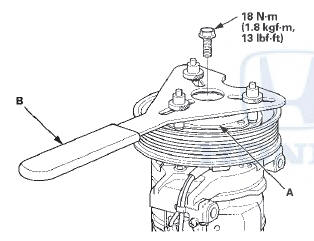
1. Remove the center bolt while holding the pressure plate (A) with a commercially available A/C clutch holder (B).
NOTE: • Do not use a hammer to remove the snap rings.
Using a hammer damages the A/C compressor.
• Do not hammer or pry on the pulley to remove it. If the pulley is difficult to remove, use a commercially available pulley removing tool. Make sure the jaws of the pulling tool engage the back face of the pulley, not the pulley grooves.
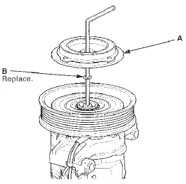
2. Remove the pressure plate (A) and the shim(s) (B), taking care not to lose the shim(s). If the clutch needs adjustment, increase or decrease the number and thickness of shims as necessary, then reinstall the pressure plate, and recheck its clearance (see page 21-73).
NOTE: • The shims are available in three thicknesses: 0.1 mm, 0.3 mm, and 0.5 mm.
• Do not pry the on the pressure plate with screwdrivers or similar tools. Prying damages the pressure plate and the pulley.
• When replacing the clutch set, place a trial stack of shims, 1 mm total thickness, on the A/C compressor shaft. Install the pressure plate, and check its clearance (see page 21-73). If the clearance is not with specification, add or substract shims as needed.
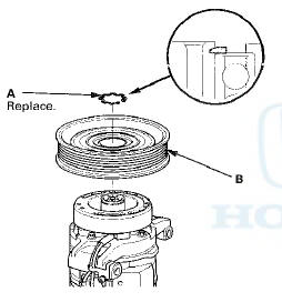
3. If you are replacing the field coil, remove the snap ring (A) with snap ring pliers, then remove the pulley (B).
Be careful not to damage the pulley or the A/C compressor.
NOTE: • Do not use a hammer to remove the snap rings.
Using a hammer damages the A/C compressor.
• Do not hammer or pry on the pulley to remove it. If the pulley is difficult to remove, use a commercially available pulley removing tool. Make sure the jaws of the pulling tool engage the back face of the pulley, not the pulley grooves.
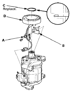
4. Remove the screw, the wire harness clip (A), and the holder (B). Remove the snap ring (C) with snap ring pliers, then remove the field coil (D). Be careful not to damage the field coil or the A/C compressor.
5. Reassemble the clutch in the reverse order of disassembly, and note these items: • When replacing the field coil, check that the new coil has the correct resistance {see step 8 on page 21-74).
• Install the field coil with the wire side facing down, and align the boss on the field coil with the hole in the A/C compressor.
• Clean the pulley and A/C compressor sliding surfaces with contact cleaner or other non-petroleum solvent.
• Install new snap rings, note the installation direction, and make sure they are fully seated in the grooves.
• Make sure that the pulley turns smoothly after it's reassembled.
• Route and clamp the wires properly, or they can be damaged by the pulley.
6. Cycle the A/C clutch approximately 20 times by running the engine at 1,500—2,000 rpm and setting the A/C system to MAX A/C mode. This procedure seats the clutch friction surfaces and increases clutch torque capacity.
 A/C Compressor Clutch Check
1. Check the pressure plate for discoloration, peeling, or
other damage. If there is damage, replace the clutch
set (see page 21-75).
2. Check the pulley bearing play and drag by rotating the
pu ...
 A/C Compressor Relief Valve
Replacement
A/C Compressor Relief Valve
Replacement
1. Recover the refrigerant with a
recovery/recycling/charging station (see page 21-80).
2. Raise the vehicle on a lift.
3. Remove the relief valve (A) and the O-ring (B). Plug
the opening to k ...
See also:
Crossover Network Control Unit
Removal/Installation
Driver's Door Speaker Crossover Network
Control Unit
1. Remove the driver's dashboard lower cover (see page
20-166).
2. Disconnect the connector (A), then remove the
driver's door speaker cross ...
DTC Troubleshooting
DTC B10A2: Driver's MICU (EEPROM) Error
NOTE: If you are troubleshooting multiple DTCs, be sure
to follow the instructions in B-CAN System Diagnosis
Test Mode A (see page 22-134).
1. Clear the D ...
Special Tools
...