 Honda Accord: Crankshaft Installation
Special Tools Required
Driver Handle, 15 x 135L 07749-0010000
Attachment, 24 x 26 mm 07746-0010700
Oil Seal Driver Attachment, 96 mm 07ZAD-PNAA100
1. M/T model: Install the crankshaft end bushing when replacing the crankshaft. Using the driver and the bearing driver attachment, 24 x 26 mm, drive in the crankshaft end bushing until the driver handle, 15 x 135L and the attachment bottom against the crankshaft.
2. Check the connecting rod bearing clearance with plastigage (see page 7-9).
3. Check the main bearing clearance with plastigage (see page 7-6).
4. Install the bearing halves in the engine block and the connecting rods.
5. Apply a coat of new engine oil to the main bearings and the rod bearings.
6. Install the crankshaft position (CKP) pulse plate to the crankshaft (see page 7-30).
7. Hold the crankshaft so rod journal No. 2 and rod journal No. 3 are straight up, and lower the crankshaft into the engine block. Be careful not to damage the journals and the CKP pulse plate.
8. Apply new engine oil to the thrust washer surfaces.
Install the thrust washers (A) in the No. 4 journal of the engine block.
9. Inspect the connecting rod bolts (see page 7-26).
10. Apply new engine oil to the threads of the connecting rod bolts.
11. Seat the rod journals into connecting rod No. 1 and connecting rod No. 4. Line up the mark (B) on the connecting rod and the cap, then install the caps and bolts finger-tight.
12. Rotate the crankshaft clockwise, and seat the journals into connecting rod No. 2 and connecting rod No. 3.
Line up the mark on the connecting rod and the cap, then install the caps and bolts finger-tight.
13. torque the connecting rod bolts to 41 N-m (4.2 kgf-m, 30 Ibf-ft).
14. Tighten the connecting rod bolts an additional 120 Р’В°.
NOTE: Remove the connecting rod bolt if you tightened it beyond the specified angle, and go back to step 9 of the procedure. Do not loosen it back to the specified angle.
15. Remove all of the old liquid gasket from the lower block mating surfaces, the bolts, and the bolt holes.
16. Clean and dry the lower block mating surfaces.
17. Apply liquid gasket, P/N 08717-0004,08718-0003, or 08718-0009 to the engine block mating surface of the lower block, and to the inside edge of the threaded bolt holes. Install the component within 5 minutes of applying the liquid gasket.
NOTE: - Apply a*3 mm (0.12 in) diamete bead of liquid gasket along the broken line (A).
- If too much time has passed after applying the liquid gasket, remove the old liquid gasket and residue, then reapply new liquid gasket.
18. Put the lower block on the engine block.
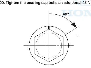
19. Apply new engine oil to the threads of the bearing cap bolts. Torque the bearing cap bolts in sequence, to 29 N-m (3.0 kgfm, 22 Ibf-ft).
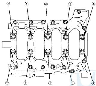
21. Torque the 8 mm bolts in sequence to 22 N-m (2.2 kgf-m, 16 Ibf-ft).
22. Apply a light coat of new engine oil to the lip of the crankshaft oil seal.
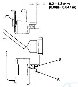
23. Use the driver handle and the oil seal driver attachment 96 mm to drive a new crankshaft oil seal squarely into the engine block to the specified installed height.
24. Measure the distance between the engine block (A) and the crankshaft oil seal (B).
Crankshaft Oil Seal Installed Height
0.2-1.2 mm (0.008-0.047 in)
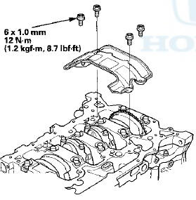
25. Install the baffle plate.
26. Install the oil pump (see page 8-23).
27. Install the oil pan (see page 7-30).
28. Install the cylinder head: - All models except PZEV (see page 6-44) - PZEV model (see page 6-94) 29. M/T model: Install the flywheel (see step 18 on page 12-18), the clutch disc (see step 26 on page 12-19), and the pressure plate (see step 27 on page 12-19).
30. A/T model: Install the drive plate (see page 14-204).
31. Install the transmission: - Manual transmission (see page 13-15) - Automatic transmission (see page 14-205) 32. Install the engine/transmission .
NOTE: Whenever any crankshaft or connecting rod bearing is replaced, run the engine at idle until it reaches normal operating temperature, then continue to run it for about 15 minutes.
 Connecting Rod Bolt Inspection
1. Measure the diameter of each connecting rod bolt at
point A and point B.
2. Calculate the difference in diameter between point A
and point B.
Point A-”Point B = Difference in Diameter
D ...
 CKP Pulse Plate Replacement
1. Remove the crankshaft from the engine block (see
page 7-14).
2. Remove the CKP pulse plate (A) from the crankshaft.
3. Install the CKP pulse plate in the reverse order of
removal. ...
See also:
Warranty Coverages
• U.S. Owners
Your new vehicle is covered by these warranties:
New Vehicle Limited Warranty – covers your new vehicle, except for the
emissions control systems and accessories, against defects ...
Navigation Communication Line Circuit
Troubleshooting
1. Operate the climate control system in several modes.
Is the climate control system OK?
YES-Go to step 2.
NO-Do the self-diagnostic function with the HDS (see
page 21-102) or climate control ...
Damper/Spring Removal and Installation
Removal
1. Raise and support the vehicle (see page 1-13).
2. Remove the front wheel.
3. Remove the wheel speed sensor harness bracket
mounting bolt (A).
4. Remove the damper pinch b ...