 Honda Accord: Countershaft Reassembly
Exploded View
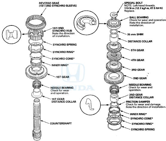
*: The components of the triple cone synchro assembly.
Special Tools Required
-СћDriver Handle, 40 mm I.D. 07746-0030100
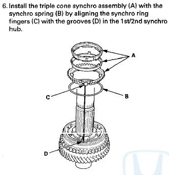
- Bearing Driver Attachment, 30 mm 07746-0030300
NOTE: Refer to the Exploded View, as needed, during this procedure.
1. Clean all the parts in solvent, dry them, and apply MTF to all contact surfaces.
2. Install the 1st gear distance collar (A) with the needle bearing (B) and 1st gear (C) onto the countershaft (D).
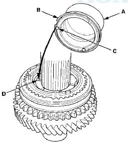
3. Install the triple cone synchro assembly (A) with the synchro spring (B) by aligning the synchro cone fingers (C) with the grooves (D) in 1st gear.
4. Install the 1st/2nd synchro hub (A) by aligning the synchro ring fingers (B) with the grooves (C) in the 1st/2nd synchro hub.
5. Install the reverse gear (A) by aligning the slots of the reverse gear and the 1st/2nd synchro hub (B). After installing, check the operation of the 1st/2nd synchro hub set.
NOTE: Make sure to align the slots in the 1 st/2nd synchro hub as shown.

7. Install the 2nd gear distance collar (A) and the friction 9- l n s t a l 1 2 n d 9 e a r ^ bV aligning the synchro cone damper (B) by aligning the friction damper fingers (C) fingers (C) with the grooves (D) in 2nd gear.
with the grooves (D) in the 1st/2nd synchro hub.
8. Install the needle bearing (A),
9. l n s t a l 1 2 n d gear (B) aligning the synchro cone
fingers (C) with the grooves (D) in 2nd gear.
11. Press on 4th gear (A) using the 40 mm I.D. driver handle (B) and a press (C).
NOTE: Do not exceed the maximum pressure.
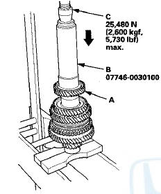
12. Press on 5th gear (A) using the 40 mm I.D. driver handle (B) and a press (C).
NOTE: Do not exceed the maximum pressure.
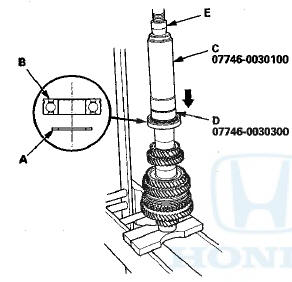
13. Install the distance collar (A), the 35 mm shim (B), and temporarily press on the used old ball bearing (C) using the 40 mm I.D. driver handle (D), the 30 mm bearing driver attachment (E), and a press (F).
NOTE: - Use any size of 35 mm shim, and note the size you used. Measurements taken in the following steps will determine the correct shim to use for final assembly.
- Make sure the ball bearing is installed in the correct direction.
14. Measure the clearance between the ball bearing (A) and the 35 mm shim (B) with a feeler gauge (C).
Standard: 0.04-0.10 mm (0.002 -0.004 in)
15. If the measured clearance in step 14 is not within the standard, select another suitable 35 mm shim from the table, then go to next step to replace the 35 mm shim and the ball bearing with new ones. If the measured clearance in step 14 is within the standard, go to the next step to replace only the ball bearing with a new one.
35 mm Shim
16. Remove the ball bearing and the 35 mm shim using a press (see step 3 on page 13-44).
17. Install the correct 35 mm shim (A) and new ball bearing (B) using the 40 mm I.D. driver handle (C), the 30 mm bearing driver attachment (D), and a press (E).
NOTE: - If necessary, replace the 35 mm shim with the correct one selected in step 15.
- Make sure the ball bearing is installed in the correct direction.
18. Check the clearance between the ball bearing and the 35 mm shim with a feeler gauge.
19. Securely clamp the countershaft assembly in a bench vise with wood blocks (A).
20. Tighten a new special bolt (B) (left-hand threads).
NOTE: Apply new MTF to the bolt threads and flange.
 Countershaft Inspection
1. Inspect the gear and bearing contact areas for wear
and damage, then measure the countershaft at points
A, B, and C. If any part of the countershaft is less than
the service limit, replace it.
...
 Synchro Sleeve and Hub Inspection and
Reassembly
Synchro Sleeve and Hub Inspection and
Reassembly
1. Inspect the gear teeth on all synchro hubs and
synchro sleeves for wear (rounded off corners).
2. Install each synchro hub (A) in its mating synchro
sleeve (B), and check for free movement. Ma ...
See also:
B-CAN System Diagnosis Test Mode
1 and Test Mode 2 (without the
HDS)
Special Tools Required
MFCS (MCIC) Service Connector 07WAZ-00101 OA
Test Mode 1
Check the ECM/PCM for DTCs and troubleshoot
ECM/PCM (see p a g e 11-3) or F-CAN loss o f
communication errors first ...
Circuit Diagram
With navigation system
Without navigation system
...