 Honda Accord: Control Unit Input Test
NOTE: Before testing, troubleshoot the multiplex integrated control unit first, using B-CAN System Diagnosis Test Mode A (see page 22-134), and make sure the lighting system works properly.
Drivers MICU
1. Turn the ignition switch to LOCK (0), and remove the driver's dashboard lower cover (see page 20-166).
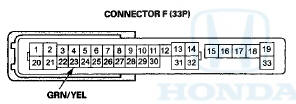
2. Disconnect driver's under-dash fuse/relay box connectors D, F, G, N, Q, and R.
NOTE: All connector views are wire side of female terminals.

*: 4-door
3. Inspect the connector and socket terminals to be sure they are all making good contact.
• If the terminals are bent, loose or corroded, repair them as necessary and recheck the system.
• If the terminals look OK, go to step 4.
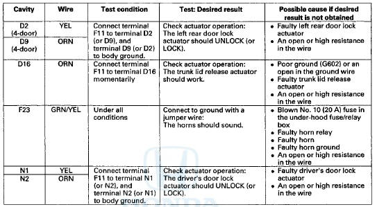
4. Reconnect connector F, and do these input tests at the following connectors.
• If any test indicates a problem, find and correct the cause, then recheck the system.
В® If ail the input tests prove OK, go to step 5.
NOTE: Before testing, make sure the No. 15 (10 A) fuse in the under-hood fuse/relay box is OK.
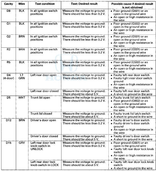
5. Reconnect the remaining connectors to the driver's under-dash fuse/relay box, and do these input tests at the following connectors. • If any test indicates a problem, find and correct the cause, then recheck the system.
• If all the input tests prove OK, go to step 6.
Passenger's MICU
6. Turn the ignition switch to LOCK (0), and remove the passenger's kick panel.
• 2-door (see page 20-105)
• 4-door (see page 20-107)
7. Disconnect passenger's under-dash fuse/relay box connectors A, D, E, and G*1 (or H*2)
*1:LX, LX PZEV, LX-P, LX-P PZEV
*2: Except LX, LX PZEV, LX-P, LX-P PZEV
NOTE: All connector views are wire side of female terminals.
CONNECTOR A (33P)
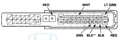
PASSENGERS UNDER-DASH FUSE/PELAY BOX CONNECTOR D (28P)
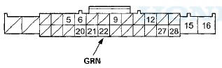
CONNECTOR E (18P)
CONNECTOR G (16P) (LX, LX PZEV, LX-P, LX-P PZEV)
CONNECTOR H (38P) (Except LX, LX PZEV, LX-P, LX-P PZEV)
* 1 : 4-door
* 2 : '08-09 models
8. Inspect the connector and socket terminals to be sure they are all making good contact.
• If the terminals are bent, loose or corroded, repair them as necessary and recheck the system.
• If the terminals look OK, go to step 9.
9. With the connectors still disconnected, do these input tests at the following connectors.
• If any test indicates a problem, find and correct the cause, then recheck the system.
• If all the input tests prove OK, go to step 10.
NOTE: Before testing, make sure the No. 15 (10 A) fuse in the under-hood fuse/relay box is OK.
*1: LX, LX PZEV, LX-P, LX-P PZEV
*2: Except LX, LX PZEV, LX-P, LX-P PZEV
10. Reconnect the connectors to the passenger's under-dash fuse/relay box, and do these input tests at the following connectors.
• If any test indicates a problem, find and correct the cause, then recheck the system.
• If all the input tests prove OK, go to step 11.
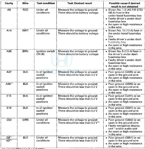
*1: LX, LX PZEV, LX-P, LX-P PZEV
*2: Except LX, LX PZEV, LX-P, LX-P PZEV
*3: With navigation system
*4: If the factory-installed audio unit or audio-navigation unit is removed from the vehicle, this voltage will be between 10-12 V.
*1:LX, LX PZEV, LX-P, LX-P PZEV
*2: Except LX, LX PZEV, LX-P, LX-P PZEV
*3: With navigation system
*4: If the factory-installed audio unit or audio-navigation unit is removed from the vehicle, this voltage will be between 10-12 V.
Door Multiplex Control Unit
11. Turn the ignition switch to LOCK (0), and open and close the driver's door, then remove the power window master switch.
• 2-door (see page 22-306)
• 4-door (see page 22-305)
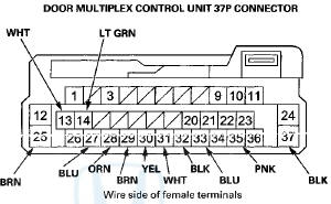
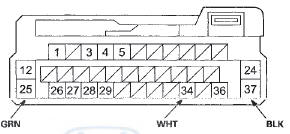
12. Disconnect the 37P connector from the door multiplex control unit.
13. Inspect the connector and socket terminals to be sure they are all making good contact.
• If the terminals are bent, loose or corroded, repair them as necessary and recheck the system.
• If the terminals look OK, go to step 14.
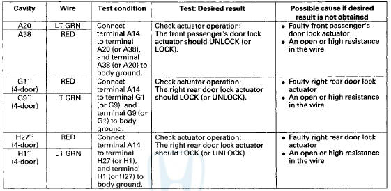
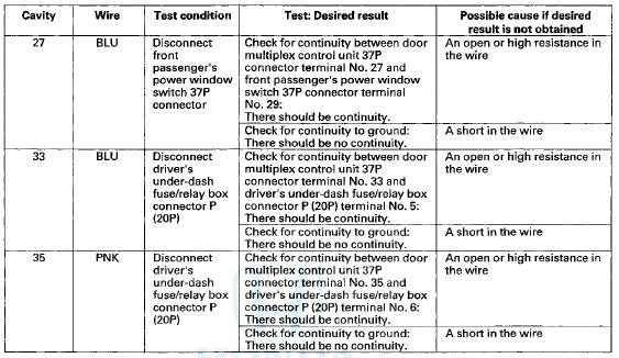
14. With the connector still disconnected, do these input tests at the following connector.
• If any test indicates a problem, find and correct the cause, then recheck the system.
• If the input test proves OK, go to step 15.
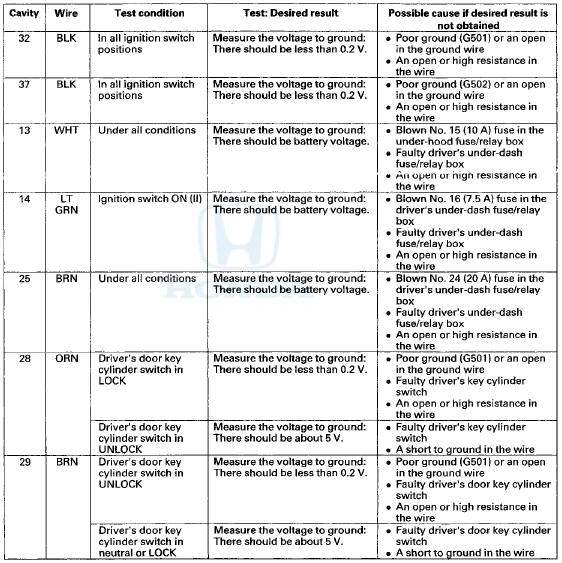
15. Reconnect the 37P connector to the door multiplex control unit, and do these input tests at the following connector.
• If any test indicates a problem, find and correct the cause, then recheck the system.
• If all the input tests prove OK, go to step 16.
Front Passenger's Power Window Switch
16. Turn the ignition switch to LOCK (0), and remove the front passenger's power window switch.
• 2-door (see page 22-307)
• 4-door (see page 22-306)
17. Disconnect the 37P connector from the front passenger's power window switch.
FRONT PASSENGERS POWER WINDOW SWITCH 37P CONNECTOR
Wire side of female terminals
18. Inspect the connector and socket terminals to be sure they are all making good contact.
• If the terminals are bent, loose or corroded, repair them as necessary and recheck the system.
• If the terminals look OK, go to step 19.
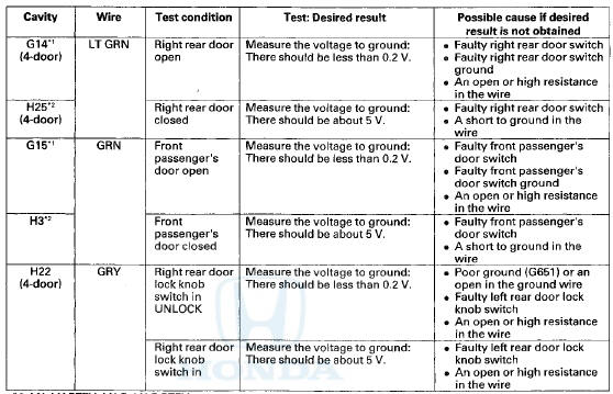
19. Reconnect the 37P connector to the front passenger's power window switch, and do these input tests at the following connector.
• If any test indicates a problem, find and correct the cause, then recheck the system.
• If all the input tests prove OK, go to step 20.
20. If multiple failures are found on more than one control unit, replace the driver's under-dash fuse/relay box (includes the driver's MICU).
• USA models (see page 22-86)
• Canada models (see page 22-87)
If input failures are related to a particular control unit, replace the control unit.
 Symptom Troubleshooting
The horn does not sound and/or the
headlights do not flash when the PANIC
button on the transmitter is pressed
NOTE: Before troubleshooting, check the B-CAN DTCs.
any DTCs are indicated, and trou ...
 Door Lock Actuator Test
Driver's Door and Left Rear Door (4-door)
1 Remove the door panel.
• Front (see page 20-17)
• Rear (see page 20-38)
2. Disconnect the 10P connector (A) from the actuator
(B).
NOTE: T ...
See also:
Steering Wheel Removal
SRS components are located in this area. Review the
SRS component locations: 4-door {see page 24-21),
2-door (see page 24-23) and the precautions and
procedures (see page 24-25) before doing repair ...
Tire Pressure Monitoring System (TPMS)
Your vehicle is equipped with a tire
pressure monitoring system (TPMS)
that turns on every time you start the
engine and monitors the pressure in
your tires while driving.
Each tire has its o ...
VSA® (Vehicle Stability Assist), aka ESC(Electronic Stability Control), System
VSA® helps to stabilize the vehicle during cornering if the vehicle turns
more or less
than what was intended. It also assists in maintaining traction on slippery
surfaces.
It does so by reg ...